The motor must be connected according to the electri-
cal codes governing the installation. The power supply
must be routed through a fused switch to protect the
motor against electrical or mechanical overloads. The
motor starter has to be set consistent with the motor
current listed on the motor nameplate.
If the pump is supplied with a manual motor starter, it is
preset at the factory in accordance with the customer’s
specification. For other voltage requirements, contact
the factory for motor and/or starter information.
Note:
See the motor manufacturer’s manual for start-
up maintenance of the motor.
Correct direction of rotation is marked by an arrow on
the motor fan housing and is counterclockwise when
looking at the motor from the motor's fan side.
1.4
Vacuum Connections
Use a line size to the vacuum system that is at least as
large as that of the pump inlet. Smaller lines will result
in lower pumping speeds than the rated values.
Install a drip leg and drain on the vertical pipe near the
pump inlet. Drain the drip leg often to prevent conden-
sation from entering the pump. Also, when installing
discharge piping, a drip leg should be installed.
If more than one vacuum pump or a receiver tank is
connected to a common main line, each pump should
have its own manual or automatic operated shut-off
valve or positive action check valve. The built-in anti-
suck-back valve should not be used as a shut-off valve
for the vacuum system.
Remove the plastic protective cap from the inlet port
prior to connection of the pump to the system. Vertical
connection of the vacuum line can be made directly to
the pump inlet (Ref. 260).
The type and size of the inlet connections of the R 5
Series pump is shown in the TECHNICAL DATA page
12.
If the gas that is pumped contains dust or other foreign
solid particles, a suitable (10 micron rating or less) inlet
filter should be connected to the inlet port. Consult the
factory for recommendations.
1.5
Oil Filling
The pump is shipped without oil. After level installation,
after correct rotation has been established and with the
pump switched "off" and secured against accidental
start-up, fill the pump with the recommended vacuum
oil through the oil filling port (Ref. 88), observing the
"MAX" and "MIN" position at the oil sight glass (Ref.
83).
Non-detergent oil should be used.
Do not use
detergent motor oil
as additives in detergent oil will
plug exhaust filter elements and shorten their life.
CAUTION: After the electrical connection
has been made, but before the pump is
filled with oil, the rotation of the motor
must be checked. Open the inlet port and
jog the motor briefly to make sure rotation
is correct. If it runs backwards and if it is
wired three phase power, reverse any two
leads of the three at the power connection.
CAUTION: Do not use the anti-suck-back
valve as a check or shut-off valve for your
vacuum system.
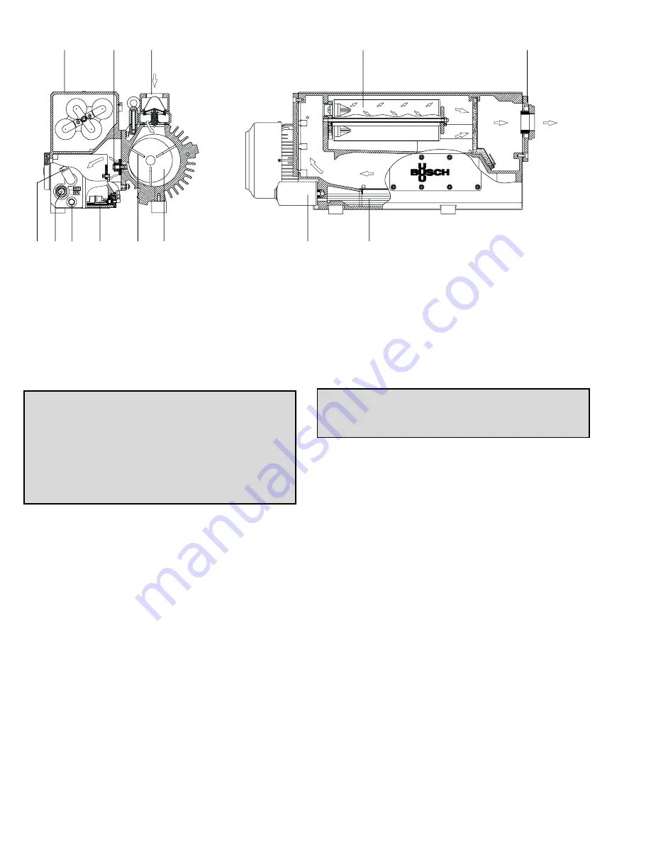
Fig. 2 - Basic R 5 RA0165, 0205, 0255 and 0305 D Series Pump
75
159
260
Inlet
100
15
22
194
95
83
90
Oil
120
140
Exhaust
3
Summary of Contents for ULTRAVAC 2100
Page 2: ......
Page 81: ......
Page 90: ...9 ...
Page 91: ...10 ...
Page 93: ...12 13 ...
Page 101: ...21 Maximum oil temperature with 80 F ambient temperature and no supplemental oil cooling ...
Page 102: ...22 ...
Page 105: ......
Page 120: ...RA 0165 0205 0255 0 0305 D Ref BMC Dwg T111 911 728 D 15 Fig 5 Exploded View Drawing of Pump ...


