


69
EMP
Installation & Service Manual
109529-03 - 11/19
Boiler
Model
Burner
Input
(GPH)
Burner
Model
Nozzle
Air
Shutter
(setting)
Air
Band
(setting)
Pump
Pressure
(PSI)
Head
Type
(setting)
Insertion
Depth
(Inch)
Approx.
Shipped
CO
2
(%)
Baffle
Location
(pass)
Approx.
Stack Temp.
Increase
Without
Baffles °F
(2)
Approx.
Breech
Pressure
(" w.c.)
(3)
Baffles
IN
Approx.
Overfire
Pressure
(" w.c.)
(3)
Baffles
OUT
Approx.
Overfire
Pressure
(" w.c.)
(3)
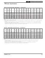
EMP84E
0.60
AFG
0.50 x 45W
Delavan
8
(1)
0
180
L2
2
11.5
2
nd
52
0
+0.010
+0.005
EMP115E
0.80
AFG
0.60 x 45W
Delavan
5
0
180
L2
2
11.5
2
nd
& 3
rd
84
0
+0.040
+0.020
EMP140E
1.00
AFG
0.75 x 60B
Delavan
9
0
180
L1
2
11.5
2
nd
65
0
+0.040
+0.020
EMP182E
1.30
AFG
1.00 X 60B
Delavan
7
1
180
V1 (0)
2
11.5
2
nd
39
0
+0.040
+0.030
EMP224E
1.60
AFG
1.25 x 60B
Hago
10
3
180
V1 (3)
2
11.5
2
nd
18
0
+0.050
+0.030
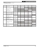
Notes
1
EMP84 at 0.60 GPH firing rate utilizes a low fire baffle.
2
The increased stack temperature with the baffles removed is an approximation, based on a constant supply temperature of 180°F and 11.5% CO
2
. Actual field conditions may
be different.
3
These values are minimum and could be as much as -.03" w.c., more without impacting performance. Pressures based on 11.5% CO
2
. Example: EMP224E could have a
breech pressure of -.03" w.c. and an overfire pressure of .020" w.c.
4
Single stage fuel pump is standard, two-stage fuel pump is optional. Burner manufacturer has preset single stage fuel pump to settings shown in table above. Two-stage
fuel pump is factory set at 140 PSI and must be readjusted to settings shown above during burner start-up.
Table 9a: Beckett AFG Burner Specifications - Chimney Vent
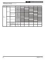
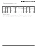
Table 9b: CARLIN EZ Burner Specifications - Chimney Vent
Boiler
Model
Burner
Input
(GPH)
Burner
Model
Nozzle
Head
Setting
Air
Setting
Pump
Pressure
(PSI)
Air Tube
Type
Insertion
Depth
(Inch)
Approx.
Shipped
CO
2
(%)
Baffle
Location
(pass)
Approx.
Stack Temp.
Increase
Without
Baffles °F
(2)
Approx.
Breech
Pressure
(" w.c.)
(3)
Baffles IN
Approx.
Overfire
Pressure
(" w.c.)
(3)
Baffles
OUT
Approx.
Overfire
Pressure
(" w.c.)
(3)
EMP84E
0.60
EZ-LF
0.50 x 60AS
Danfoss
1.0
30
150
12D
2-5/8
11.5
2
nd
52
0
+0.040
+0.020
EMP115E
0.80
EZ-LF
0.65 x 60AS
Danfoss
0.75
65
150
12D
2-5/8
11.5
2
nd
& 3
rd
84
0
+0.040
+0.020
EMP140E
1.00
EZ-66
0.85 x 45AS
Danfoss
2.0
40
150
Conical
Wrap
2-5/8
11.5
2
nd
65
0
+0.040
+0.020
EMP182E
1.30
EZ-66
1.10 x 45B
Delavan
3.5
50
150
Conical
Wrap
2-5/8
11.5
2
nd
39
0
+0.040
+0.030
EMP224E
1.60
EZ-66
1.35 x 45B
Delavan
5.5
60
150
Conical
Wrap
2-5/8
11.5
2
nd
18
0
+0.050
+0.030
Notes
2
The increased stack temperature with the baffles removed is an approximation, based on a constant supply temperature of 180°F and 11.5% CO
2
. Actual field
conditions may be different.
3
These values are minimum and could be as much as -.03" w.c., more without impacting performance. Pressures based on 11.5% CO
2
. Example: EMP224E
could have a breech pressure of -.03" w.c. and an overfire pressure of .020" w.c.
4
Single stage fuel pump is standard, two-stage fuel pump is optional. Burner manufacturer has preset single stage fuel pump to settings shown in table above.
Two-stage fuel pump is factory set at 140 PSI and must be readjusted to settings shown above during burner start-up.
14
Burner Specifications


