


14
EMP
Installation & Service Manual
109529-03 - 11/19
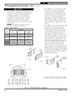
a. By design, cast bars on front section between
the combustion chamber and between the left
and right side 2
nd
and 3
rd
pass flueway should
make an impression in door insulation to seal
the chambers.
b. By design, door insulation on model
EMP224E will have two (2) by-pass pockets
cast into the insulation centered on the bar
between the combustion chamber and 3rd
pass flueways.
On models EMP84E thru EMP182E these
pockets should not be present. If insulation
is damaged or not of proper type regarding
pockets, it must be replaced.
4. Do not close and secure door at this time,
proceed to Field Assembly Details, Paragraph
F.
F .
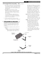
FIELD ASSEMBLY OF BOILER TRIM
Open
miscellaneous parts carton and remove contents.
Identify the components using the illustrations
(see Figure 5 thru 8) throughout the assembly
sequence outlined below as it applies to your
installation.
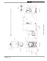
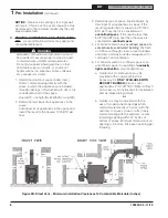
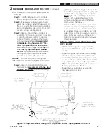
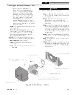
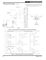
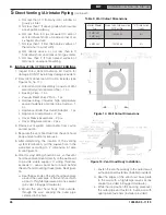
1. Install return manifold and relief valve, refer to
Figure 5.
Step a.
Locate the return pipe fittings and
injector. Apply sealant to the 2" NPT
injector threads. Insert injector into 2"
Figure 5: Return Manifold and Relief Valve Assembly Details
NPT upper rear tapping on rear section.
Thread 2" NPT x 1-1/2" Reducing Elbow
onto 2" NPT injector. Apply thread
sealant to the 1-1/2" NPT nipple. Thread
1-1/2" nipple into 1-1/2" NPT end of
reducing elbow. Thread 1-1/2" NPT x
1-1/2" NPT x 3/4" NPT Tee onto 1-1/2"
NPT nipple. Tighten pipe fittings until
relief valve orientation is correct for your
installation and joints are watertight.
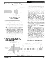
Note
: Based on system return piping and
access to service boiler, see Figures
1, 9A and 9B, predetermine if manifold
orientation is to be positioned for
vertical, horizontal left or horizontal right
side return piping as shown in Figure 5.
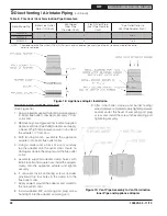
Step b.
Install relief valve using 3/4" NPT
tapping on tee. Relief valve must
be installed in vertical position. If
orientation of return manifold is for:
• 1-1/2" NPT vertical return piping -
Install 3/4" NPT x 90º street ell (not
furnished) inot 3/4" NPT tapping on
tee. Install relief valve vertically into
street ell. See Figure 9.
• 1-1/2" NPT horizontal left or right
side return piping - Install relief valve
vertically in 3/4" NPT tapping on tee.
See Figure F4.
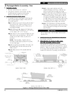
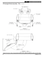
2
Packaged Boiler Assembly - Trim
(continued)


