


53
EMP
Installation & Service Manual
109529-03 - 11/19
A .
COMBUSTION
1. NOZZLES — Although the nozzle is a relatively
inexpensive device, its function is critical to
the successful operation of the oil burner. The
selection of the nozzle supplied with the EMP
boiler is the result of extensive testing to obtain
the best flame shape and efficient combustion.
Other brands of the same spray angle and spray
pattern may be used but may not perform at the
expected level of CO
2
and smoke. Nozzles are
delicate and should be protected from dirt and
abuse. Nozzles are mass-produced and can vary
from sample to sample. For all of those reasons a
spare nozzle is a desirable item for a serviceman
to have.
2. FLAME SHAPE — Looking into the combustion
chamber through the observation port, the flame
should appear straight with no sparklers rolling
up toward the crown of the chamber. If the flame
drags to the right or left, sends sparklers upward or
makes wet spots on the chamber walls, the nozzle
should be replaced. If the condition persists look
for fuel leaks, air leaks, water or dirt in the fuel as
described above.
3. FUEL LEAKS — Any fuel leak between the
pump and the nozzle will be detrimental to good
combustion results. Look for wet surfaces in the
air tube, under the ignitor, and around the air
inlet. Any such leaks should be repaired as they
may cause erratic burning of the fuel and in the
extreme case may become a fire hazard.
4. AIR LEAKS — Any such leaks should be repaired,
as they may cause erratic burning of the fuel and
in extreme cases may become a fire hazard.
5. GASKET LEAKS — If 11.5 to 12.5% CO
2
with a
#1 smoke cannot be obtained in the breeching,
look for air leaks around the burner mounting
gasket, observation door, and canopy gasket.
Such air leaks will cause a lower CO
2
reading in the
breeching. The smaller the firing rate the greater
effect an air leak can have on CO
2
readings.
6. DIRT — A fuel filter is a good investment.
Accidental accumulation of dirt in the fuel system
can clog the nozzle or nozzle strainer and produce
a poor spray pattern from the nozzle. The smaller
the firing rate, the smaller the slots become in the
nozzle and the more prone to plugging it becomes
with the same amount of dirt.
7. WATER — Water in the fuel in large amounts will
stall the fuel pump. Water in the fuel in smaller
amounts will cause excessive wear on the pump,
but more importantly water doesn’t burn. It chills
8. COLD OIL — If the oil temperature approaching
the fuel pump is 40°F or lower, poor combustion
or delayed ignition may result. Cold oil is harder
to atomize at the nozzle. Thus, the spray droplets
get larger and the flame shape gets longer. An
outside fuel tank that is above grade or has fuel
lines in a shallow bury is a good candidate for
cold oil. The best solution is to locate the tank
near the boiler in the basement utility room or
bury the tank and lines deep enough to keep the
oil above 40°F. Check environmental issues with
local authorities having jurisdiction.
9. HIGH ALTITUDE INSTALLATIONS — Air
openings must be increased at higher altitudes.
Use instruments and set for 11.5 to 12.5% CO
2
.
10. START-UP NOISE — Late ignition is the cause of
start-up noises. If it occurs recheck for electrode
settings, flame shape, air or water in the fuel lines.
11. SHUT DOWN NOISE — If the flame runs out
of air before it runs out of fuel, an after burn with
noise may occur. That may be the result of a
faulty cut-off valve in the fuel pump, or it may be
air trapped in the nozzle line. It may take several
firing cycles for that air to be fully vented through
the nozzle. Water in the fuel or poor flame shape
can also cause shut down noises.
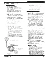
NOTICE:
CHECK TEST PROCEDURE. A very
good test for isolating fuel side problems is to
disconnect the fuel system and with a 24" length
of tubing, fire out of an auxiliary five gallon pail of
clean, fresh, warm #2 oil from another source. If
the burner runs successfully when drawing out of
the auxiliary pail then the problem is isolated to
the fuel or fuel lines being used on the jobsite.
B .
OIL PRIMARY CONTROL (Oil Primary)
1. Burner (Oil Primary) will not come on.
a. No power to Oil Primary.
b. Oil Primary is in lockout or restricted mode.
Press reset button for one (1) second to exit
lockout. If control has recycled three times
within the same call for heat, it will enter into
restricted mode. To reset from restricted
mode, refer to Section VIII, Paragraph J, No.
2 for details.
c. CAD cell seeing light.
d. CAD assembly defective.
e. Control motor relay is stuck closed (see
note below).
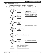
12
Troubleshooting
the flame and causes smoke and unburned fuel
to pass out of the combustion chamber and clog
the flueways of the boiler.


