


43
EMP
Installation & Service Manual
109529-03 - 11/19
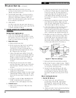
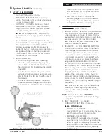
Figure 33: R7284 Oil Primary Terminals,
Display and Function Buttons
•
Check contacts between ignitor and the
electrodes.
•
Check the oil pump pressure.
•
Check the piping to the oil tank.
•
Check the oil nozzle, oil supply and oil filter.
b. Check Safety Features
Safe Start:
•
Place a jumper across cad cell terminals.
•
Follow procedure to turn on burner
Burner must not start, indicator light turns
on and control remains in Idle Mode.
•
Remove jumper.
c. Simulate Ignition or Flame Failure:
•
Follow procedure to turn on burner.
•
Check cad cell resistance. If resistance is
below 1600 OHMS and burner runs
beyond safety cut-out time, cad cell is
good.
•
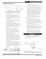
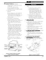
If safety switch shuts down burner and
resistance is above 1600 OHMS, open
line switch to boiler. Access cad cell
under ignitor, clean face of cad cell
and see that cell is securely in socket,
see Figure 34. Check gasket around
perimeter of ignitor lid for proper seal.
If gasket is missing or damaged, replace
gasket. Room light can effect cad cell
resistance. Reset safety switch.
•
Close line switch to boiler. If burner
starts and runs beyond safety switch cut-
off time, cell is good. If not, install new
cell.
•
Close hand valve in oil supply line.
•
Failure occurs, device enters Recycle
Mode.
Figure 34: Cad Cell Location
K . CHECK HIGH LIMIT
1. Adjust system thermostat(s) to highest setting.
2. Allow burner to run until boiler water
temperature exceeds high limit setting. The
burner should shut down and circulators
continue running.
3. Allow the temperature to drop below control
setting. The burner must restart.
4. Boiler installation is not considered complete
until this check has been made.
L . IF CONTROLS MEET REQUIREMENT
outlined
in Paragraphs I thru K.
1. Allow boiler to operate for approximately 30
minute, confirm the boiler and system have no
leaks.
2. Reset thermostat(s) at desired setting.
M .
IF CONTROLS DO NOT MEET
REQUIREMENTS
outlined in Paragraphs I
thru K, replace control and repeat checkout
procedures.
WARNING
Cad Cell Jumper must be removed after this
check.
8
System Start-Up
(continued)
!
•
Device tries to restart system after
approximately 60 seconds.
•
After third Recycle Mode trial, safety
switch locks out within safety switch
timing indicated on label and control
enters Restricted Mode. Ignition and
motor stop and oil valves closes.
d. Power Failure Check: After Flame is
established, turn the power off to the
control/burner. The burner should shut
down safely. When power is restored a
normal ignition sequence should be started.


