


27
EMP
Installation & Service Manual
109529-03 - 11/19
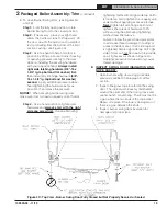
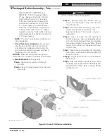
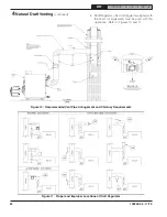
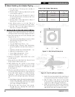
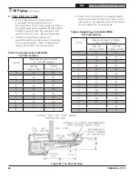
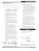
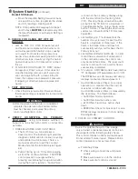
Figure 16: Combustion Air Tee
Assembly Installation
C . INSTALLATION OF VENT HOOD TEE
1. Assemble the vent hood tee body to the vent hood
outer pipe, and, rotate the tee, so air intake inlet
collar is in the desired position. See Figure 16.
2. Attach the vent hood tee body to the vent hood
outer pipe with at least tree sheet metal screws
(installer provided).
Note:
The tee may be rotated into any position so
that the collar is in a convenient orientation.
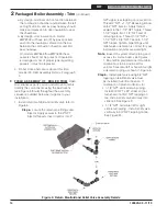
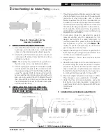
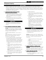
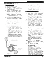
3. After completing assembly of the flexible double
wall insulated vent pipe to the vent termination
inner pipe (see Figure 17 and the following Steps),
apply the supplied high temperature sealant to
seal around the inner pipe protrusion thru the vent
tee cover pan, around the joint between the vent
tee collar and the vent tee body, and, seal or tape
the joint between the vent termination outer pipe
and the vent tee body.
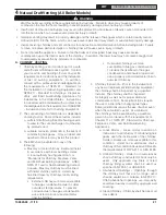
D . INSTALLING THE FLEX OIL VENT PIPE
FROM THE VENT TERMINATION TO THE
BOILER FLUE OUTLET
1. The venting system (vent pipe and all connectors)
shall be installed in accordance with the applicable
provisions of any local codes, and, in United
States, requirements of NFPA 31-
Standard for the
Installation of Oil-Burning Equipment
and
NFPA
211 Standard for Chimney, Fireplaces, Vents and
Solid Fuel-Burning Appliances
, latest editions.
For installations in Canada, follow requirements
of CSA B139 - Installation Code for Oil Burning
Equipment, latest edition.
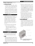
2. A vent pipe connector, designed for positive
pressure venting, shall be supported for the
design and weight of material employed, to
maintain clearances, prevent physical damage
and separation of joints. All joints
MUST BE
sealed, for positive vent pressure, to prevent flue
gas leakage into the structure.
3. Support the vent pipe at intervals no greater than
three (3) feet apart using perforated metal strap
or other non-combustible supports.
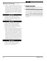
4. Allow sealant to cure at least one hour before
firing boiler.
5. Route the vent pipe from the vent termination to
the boiler using the minimum number of bends
possible. The last horizontal section of the vent
pipe should have a slight downward slope from
the boiler to the vent termination. For clearances
to combustible materials refer to Figure 2B.
6. Maximum length of flexible oil vent pipe is 20 ft.
The vent pipe is also available in 10 ft length.
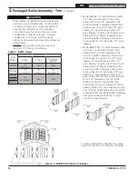
7. Verify that flex vent pipe diameter and vent
termination inner pipe diameter correspond to
a particular direct vent configuration EMP boiler
model (see
Table 6).
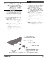
E .
CONNECTING APPLIANCE ADAPTER TO
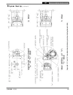
Figure 17: FDVS Component Breakdown
5
Direct Venting / Air Intake Piping
(continued)


