


30
EMP
Installation & Service Manual
109529-03 - 11/19
G .
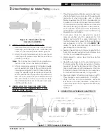
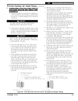
INSTALLING THE AIR INTAKE PIPING FROM
DIRECT VENT TERMINATION TO BURNER
OUTSIDE AIR ADAPTER
1. Use 4" diameter galvanized single wall vent pipe
and fittings, available at most heating distributors,
to connect burner outside air adapter to Direct
Vent Termination air intake collar.
2. Maximum air intake pipe length is 40 equivalent
feet.
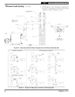
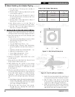
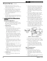
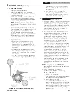
Figure 21: Vent Pipe Assembly to Vent Termination
Inner Pipe & Appliance Adapter
WARNING
DO NOT reduce size of air intake pipe.
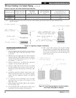
3. Start at burner and work towards Direct Vent
termination.
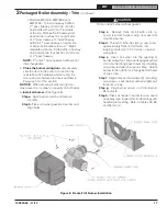
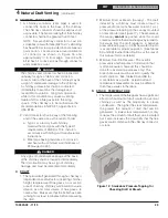
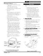
4. Remove burner cover. Loosen two screws
securing outside air duct bracket to burner
cover mounting plate. See Figure 22.
5. Procure a 2-ft section of 4" diameter galvanized
single wall vent pipe, cut off the crimped pipe
end below stop bead.
6. Insert one end of the vent pipe thru the outside
air duct bracket opening and firmly push onto
the outside air adapter collar.
7. Secure the pipe to collar with at least (3)
sheet metal screws (installer provided) evenly
spaced around the collar.
8. Re-tighten the screws securing outside air duct
bracket to burner cover mounting plate.
NOTICE:
It is essential to ensure reliable
operation that combustion air joints are air tight
and that VRV is located as close to the burner as
possible.
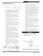
9. Install supplied vacuum relief valve tee assembly,
crimped end down, into the opposite end of vent
pipe.
10. Secure the tee to the pipe with at least (3) sheet
metal screws (installer provided) evenly spaced.
11. Remove the vacuum relief valve gate assembly
from the tee.
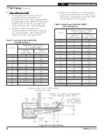
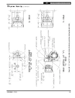
Figure 22: Oil Burner Installation (Beckett shown)
5
Direct Venting / Air Intake Piping
(continued)
!


