


40
EMP
Installation & Service Manual
109529-03 - 11/19
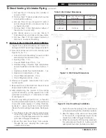
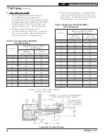
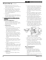
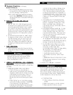
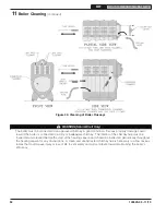
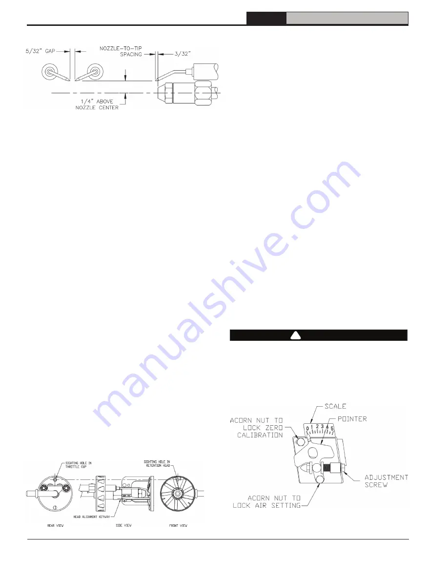
Figure 29: Electrode Tip Gap and Spacing
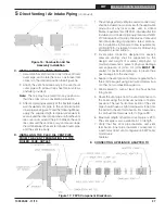
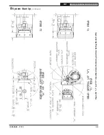
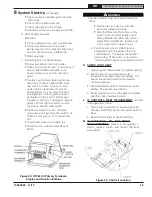
Figure 30: Retention Head/Throttle Cup Alignment
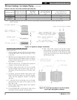
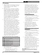
Figure 31: Head/Air Adjustment Plate Assembly
c. Disconnect the copper oil connector tube
from nozzle line.
d. Loosen the two screws securing igniter-
retaining clips and rotate both clips to
release the igniter baseplate. The igniter
should pop-up and would be supported by
the prop spring.
e. Loosen the two screws securing the rear
door, then swing to the right and down.
f. Loosen splined nut.
g. Lift up the igniter baseplate and
simultaneously remove nozzle line assembly
from burner by drawing it straight back out
the rear door opening. Be careful not to
damage the electrodes or insulators while
handling.
h. Check electrodes to comply with
dimensions shown in Figure 29. For
adjustment, loosen the electrode clamp
screw and slide /rotate electrodes as
needed. Securely re-tighten the clamp
screw when finished.
i. Check retention head alignment. Cad
cell sighting holes in the throttle cup and
retention head must line up, so the cad
cell can see the flame. Make sure that the
"stamped key" in the retention head collar
lines up with the "keyway" in the nozzle
adapter, when mounting the retention head.
See Figure 30.
j. To re-install the nozzle line assembly,
reverse procedure outlines in steps f thru b.
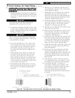
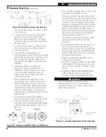
k. Upon reinstallation of the nozzle line
assembly, check that head/air plate setting
number pointer line up with a number on
the scale,
which matches a value shown in Table 10 for
a particular boiler/burner model.
The zero calibration has been factory set;
the upper left acorn nut locks retention head
at “0” position. If the zero calibration has to
be reset, follow the adjustment procedure,
outlined at “Prepare Burner & Site” section
of Beckett Model NX Oil Burner Instruction
Manual, Form Number 610BNX. Make
sure the retention head is securely against
the stops in the retention ring, when the
adjustment plate pointer is at “0”.
l. The rear door must be kept tightly closed
upon reinstallation of the nozzle line
assembly.
m. Loosening the splined nut and lower acorn
nut, and, turning the adjustment screw,
either forward or, rearwards, will adjust the
head/air plate. DO NOT LOOSEN UPPER
LEFT ACORN NUT, which locks zero head/
air setting. See Figure 31.
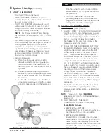
n. OPEN ALL SHUT-OFF VALVES in the oil
supply line to the burner.
o. ATTACH A PLASTIC HOSE TO FUEL PUMP
VENT/BLEED FITTING and place the other
hose end into an empty container to catch
the oil.
p. SLIGHTLY OPEN FLAME OBSERVATION
PORT COVER on burner swing door,
enough to insert draft gauge probe later.
WARNING
Very hot flue gases come out of flame
observation port cover hole when boiler is
operated with port cover open. Always wear
proper eye protection.
8
System Start-Up
(continued)
!


