


26
EMP
Installation & Service Manual
109529-03 - 11/19
c. Not less than 1 ft from any door, window or
gravity air inlet.
d. Not less than 7 ft above grade when located
above public walkway.
e. Not less than 3 ft (as measured to side of
vent termination) from an inside corner of an
L-shaped structure.
f. Not less than 1 ft from the nearest surface of
the terminal to a roof soffit.
g. Not directly above, or, not less than 6 ft
horizontally from an oil tank vent or gas meter.
h. Not less than 2 ft from nearest surface of
terminal to an adjacent building.
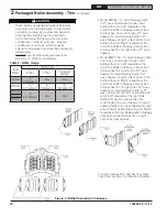
B . INSTALLATION OF THE VENT HOOD TERMINAL
1. Inspect Direct Vent Conversion Kit Carton for
damage. DO NOT install if any damage is evident.
2. Direct Vent Conversion Kit Carton includes (see
Figures 15, 16, 17):
• Direct Vent Hood Assembly (consists of Vent
Hood Body and Vent Hood Tee) – 1 pc
• Backing Plate – 1 pc
• Vacuum Relief Valve VRV-4 – 1 pc
• Hardware Bag (includes high temperature
sealant, fasteners and inner pipe clamps) – 1
pc
• Appliance (Boiler Flue Outlet) Adapter – 1 pc
• Appliance Clamp Halves – 2 pcs
• Cover Sleeve Assemblies – 2 pcs
• Cover Ring Assemblies – 2 pcs
3. Remove vent system components from carton
and set aside.
4. Separate the vent hood tee from the vent hood
body and set aside for later use.
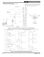
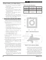
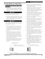
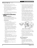
5. After determining the location of the venting
system termination, cut the square hole in the
wall sized according to “L” dimension in Table
5, see Figure 14.
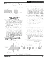
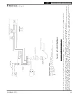
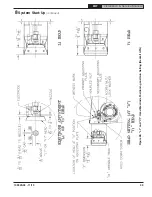
6. Wood or vinyl siding should be cut, so that vent
hood base plate mounts directly on the wallboard
to provide stable support. If siding thickness
exceeds ½”, use a spacer bar or board behind
the vent hood mounting (base) plate. See Figure
15.
a. Seal the backside of the vent hood base plate
around the outer pipe of the vent hood with
a bead of high-temperature silicone sealant
(provided in Bagged Hardware).
b. Mount the vent hood body from outside,
through the wall, keeping the outer pipe
centered in the hole.
Boiler Model
No.
Direct Vent Conversion
Kit Part No.
"L" Dimension
(Inch)
EMP140E
EMP182E
102130-02
8¼
EMP224E
102130-03
9¼
Table 5: Wall Cutout Dimensions
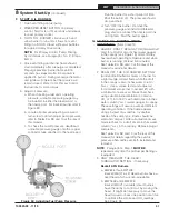
Figure 14: Wall Cutout Dimensions
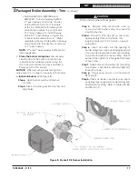
Figure 15: Vent Hood Body Installation
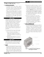
c. Fasten the vent hood body to the outside wall
with appropriate fasteners (installer provided).
d. Seal the edges of the vent hood base plate
to the wall with a high-temperature silicone
sealant (provided in Bagged Hardware).
e. While inside, position the backing plate over
the outer pipe and fasten to inside wall with
appropriate fasteners (installer provided).
5
Direct Venting / Air Intake Piping
(continued)


