


29
EMP
Installation & Service Manual
109529-03 - 11/19
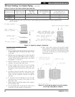
3. Pull outer vent pipe back 1” to 2” from end of
inner vent pipe and remove insulation; firstly,
at vent pipe end to be connected to the vent
termination; secondly, at vent pipe end to
be connected to the appliance adapter. See
Figure 19.
4. Install supplied Cover Sleeve Assembly onto
each end of outer vent pipe, and, move the
assembly a few inches back from the end;
firstly, at vent pipe side to be connected to the
vent termination; secondly, at vent pipe side
to be connected to the appliance (boiler outlet
collar) adapter. See Figure 19.
5. Slide supplied Cover Rings; firstly, over stop
bead on vent termination inner pipe; secondly,
over stop bead on appliance adapter. See
Figure 19.
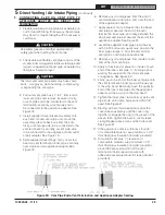
6. Remove any oil and grease from the end of
vent termination inner pipe, and, from the end
of the appliance adapter.
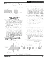
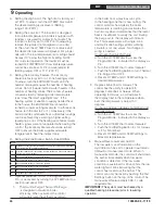
7. Apply sealant; firstly, between the stop bead
and retainer bead at the end of the vent
termination inner pipe; secondly, between the
stop bead and retainer bead at the end of the
appliance adapter. See Figure 20.
8. Assemble supplied inner pipe clamp halves
with 1/4-20 bolts and square nuts; position the
inner pipe clamps ¼” from the end of inner
vent pipe, on vent pipe opposite ends.
9. Remove any oil and grease from inside of each
end of the inner vent pipe.
10. Apply a thick bead of sealant to inside of each
end of the inner vent pipe, ½” from pipe end,
working the sealant into the inner vent pipe
corrugations. See Figure 20.
11. Firstly, push one end of the inner vent pipe onto
the vent termination inner pipe, all the way up
to the stop bead. Secondly, push the opposite
end of the inner vent pipe onto the appliance
adapter, all the way up to the stop bead.
12. Tighten the inner pipe clamp bolts at both vent
pipe ends, until clamp halves are within 1/8”
apart. See Figure 21.
13. Starting with vent termination end, slide the
cover sleeve assembly and the cover ring
together to engage the ring in the groove of the
sleeve, then, tighten the built-in cover sleeve
clamp. Repeat above steps at the boiler end.
See Figure 21.
14. If the appliance collar is within less than 18"
of combustible material, wrap minimum 1-1/2"
thick fiberglass insulation (installer provided).
15. To maintain vent pipe 1" clearance to
combustible material, wrap minimum 1-1/2"
thick fiberglass insulation (installer provided)
around the exposed portion of the vent
termination inner pipe and secure with
adhesive-backed aluminum foil tape (installer
provided).
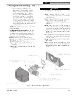
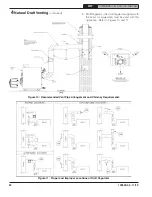
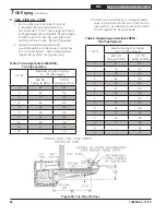
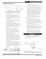
Figure 20: Vent Pipe Ends, Vent Termination and Appliance Adapter Sealing
F . CONNECTING FLEX OIL VENT PIPE TO
APPLIANCE ADAPTER AND DIRECT VENT
TERMINATION
1. Flexible double wall oil vent pipe is available pre-
cut 10 ft and 20 ft long. If necessary, the vent pipe
may be cut to required length with a hacksaw or
cutoff saw.
CAUTION
Use safety glasses and other appropriated
safety gear when cutting the vent pipe.
2. The double wall flexible vent pipe consists of the
smaller inner corrugated stainless steel pipe and
larger corrugated aluminum pipe, separated by
fiberglass insulation layer.
CAUTION
The inner and outer pipe ends may have sharp
burrs. Use gloves, while handling, compressing
or expanding the vent pipe.
5
Direct Venting / Air Intake Piping
(continued)
!
!


