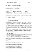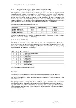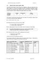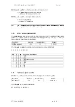
XIIMUS 4K CL User Manual. Model: 4096CT. Version 1.4
C4
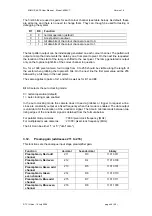
Camera Link. 30 bit RGB (IR, R, GB) for Medium or Dual Base
configuration in quad 8 bit mode (24 bit RGB + LSB byte on second
connector)
C5
Camera Link. Multiplexed colour channels, 8 bits for Base
configuration. Order of the colours is RGB (IR, R, GB).
C6
Camera Link. Multiplexed colour channels, 8 bits for Base
configuration. Order of the colours is BGR (GB, R, IR).
C7
Camera Link. Multiplexed colour channels, 10 bits for Base
configuration. Order of the colours is RGB (IR, R, GB).
C8
Camera Link. Multiplexed colour channels, 10 bits for Base
configuration. Order of the colours is BGR (GB, R, IR).
C9
Camera Link. Multiplexed colour channels, 12 bits for Base
configuration. Order of the colours is RGB (IR, R, GB).
C10
Camera Link. Multiplexed colour channels, 12 bits for Base
configuration. Order of the colours is BGR (GB, R, IR).
C11
Camera Link. 36 bit RGB (IR, R, GB) for Dual Base configuration
C12
Camera Link. 36 bit RGB (IR, R, GB) for Medium configuration
Note:
Each Camera Link camera contains either all the modes C5 to C10 or all the
other modes. The selection within each group is user programmable.
6
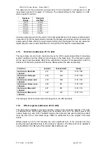
Initial serial communications port for Camera Link models
A
RS-232 via the standard 9-pin D-connector
B
Camera
Link
®
specification
Please leave this field blank for LVDS cameras.
Note:
Users can change this setting.
7
Read-out rate of each colour channel
40
40 MHz for parallel output only. Camera Link and LVDS.
33
33 MHz for parallel output only. Camera Link and LVDS.
25
25 MHz for parallel output only. Camera Link and LVDS.
20
20 MHz for parallel output only. Camera Link and LVDS.
16
16.7 MHz for multiplexed Camera Link output only.
08
8.3 MHz for multiplexed output only.
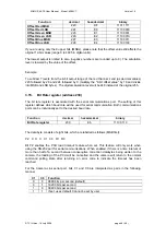
Example:
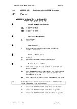
XIIMUS 1024-CT-14-P-A-25 has three 1024 pixel sensors of 14 µm x 14 µm
pixel size, each at 25 MHz pixel rate. The data interface is CameraLink, but the
serial communication is set to use the standard 9-pin RS-232 connector.
© TVI Vision, 14 July 2006 page 52 ( 56 )

