XIIMUS 4K CL User Manual. Model: 4096CT. Version 1.4
3.3.3.
Read Hardware Settings
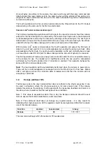
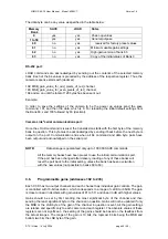
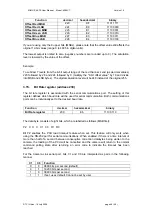
This command will reply with two bytes. The first byte of the reply consists of eight bits, which
are labelled as follows (MSB first):
X X M CL T1 T0 V1 V0
Bit M defines if the camera has parallel or multiplexed output:
0 = Parallel output
1 = Multiplexed output
Bit CL indicates whether the camera is with LVDS or Camera Link output
0 = LVDS
1 = Camera Link
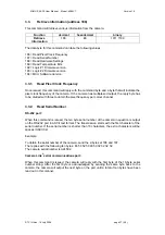
Bits T1 and T0 are interpreted as pairs and are used to distinguish various custom versions
of the camera from base models
T1 T0
Interpretation
0
0
TVI basic model
0 1
Custom
0
1 0
Custom
1
1 1
Custom
2
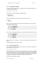
Bits V1 and V0 are interpreted as pairs and are used to indicate the pixel count of the camera
V1 V0
Interpretation
0 0
1024
pixels
0 1
2048
pixels
1 0
4096
pixels
1 1
512
pixels
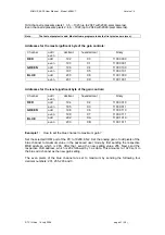
Please contact TVI, if this setting is not correct, as it will affect correct operation of the
camera.
The second data byte is reserved for future use.
3.3.4.
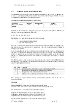
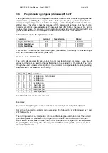
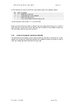
Read Temperature Bits
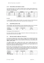
This command will reply with the command byte and a second byte that will indicate the
internal temperature level as follows:
X X X X X X T1 T0
When both bits T0 and T1 are zeroes, the camera temperature level is ok. When T0 is goes
high, a temperature warning is issued, but the camera works normally. A red LED labelled
‘Temp error’ will also light up in the camera backplane to indicate the condition. When the
second bit T1 goes high as well, camera image aquisition will be halted and the camera must
be rebooted once it has cooled. Serial ports will continue to function normally.
The bits marked X are zeroes by default.
© TVI Vision, 14 July 2006 page 38 ( 56 )

