XIIMUS 4K CL User Manual. Model: 4096CT. Version 1.4
TEMP ERR, red
ON:
Warning of too high an internal temperature. If the camera cools
down, this warning will be removed, but if the temperature rises
further the camera will be stopped permanently until the next
power-up. Please note that this is only an early warning of high
operating temperature and that it is permitted to use the camera
even when this warning is continuously on. The status of
temperature monitoring can be read via serial communications.
5.3 Data
Connector
Two MDR-26 connectors handle the data communication according to the Camera Link
specification. The connectors are labelled CL1 and CL2. CL1 is for Base Configuration. Both
connectors are needed for Medium and so called Dual Base (non-standard) Configurations.
Cables can be secured with either screw locks or latches.
All signals are specified by the Camera Link standard, except the four Camera Control inputs:
CC1
NewLine
- the rising edge defines the change-of-line moment (after a constant delay)
- period is the line rate
CC2
Exposure Control Red (or all channels)
- exposure control signal for the Red channel
- the effect for this is defined by the mode that is selected via
RS-232 interface or Camera Link serial port
- as default this signal is common to all the three CCDs
- a low level resets all the pixels
- should be constantly high, if full time exposure is needed
- a constant '0' results in dark images
CC3
Exposure Control Green
- exposure control signal for the Green channel when camera is set to
individual exposure control mode
CC4
Exposure Control Blue
- exposure control signal for the Blue channel when camera is set to
individual exposure control mode
For cabling please refer to the Camera Link specifications. TVI Vision also provides Camera
Link cables. Please contact sales ([email protected]).
All the input signals are internally terminated by 100
Ω
resistors.
All the output signals should be terminated respectively (one 100
Ω
resistor connected
between the positive and negative wire of each signal pair).
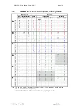
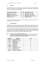
Appendix A shows the output bit port assignments of all the available Camera Link modes.
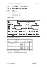
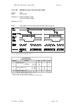
Appendix B presents the timing details of the interface signals.
© TVI Vision, 14 July 2006 page 18 ( 56 )

