XIIMUS 4K CL User Manual. Model: 4096CT. Version 1.4
6. MECHANICAL
STRUCTURE
6.1
Mechanical dimensions and mounting of the camera
The mechanical structure of the camera provides a compact entity to meet the rigid de-
mands of the industrial environment. The camera case is aluminium, which provides an
excellent electrical protection against external electromagnetic interference. When selecting
the components, corrosion resistance has also been considered.
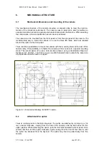
The camera can be mounted from the front panel or from the side panel of the camera. The
recommended way to mount the camera is to use the three M5 holes, which are situated
around the optics on the front panel.
There are three possibilities to mount the camera with the mounting holes at the side of the
camera body. First possibility is to fasten the camera with four screws to a special mounting
stand. The second option is to use a normal camera tripod, using a standardised tripod at-
tachment 1/4", 20 UNF. The third is to use two M6 threaded holes to attach the camera to
any application specific frame or support.
Figure 6.1. Dimensional drawing of 4096CT camera.
6.2
Attachment for optics
There is a locking latch in the Nikon bayonet. The optics are attached by turning it (ca. 1/4
rev.) counter clockwise, viewing from the front of the camera, until the latch rises into the
upper position. When detaching the optics, push the latch first towards the front panel of the
camera and then turn the optics clockwise, again viewing from the front of the camera, until
the optics are released from the bayonet. The optics may then be pulled away from the
camera.
© TVI Vision, 14 July 2006 page 20 ( 56 )

