XIIMUS 4K CL User Manual. Model: 4096CT. Version 1.4
5. CAMERA
INTERFACE
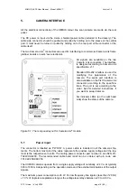
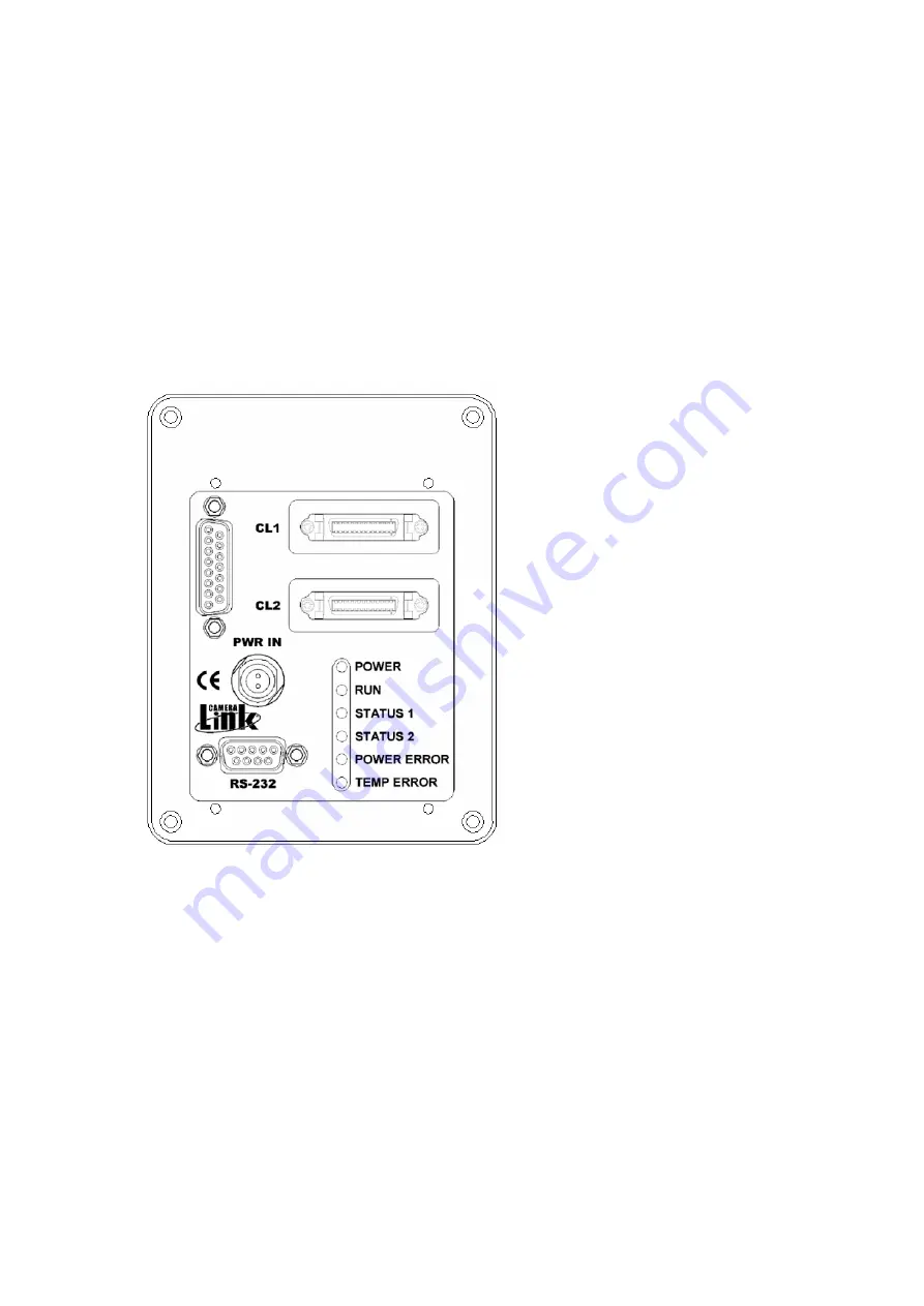
All the electrical connections of the XIIMUS colour line scan camera are made via the rear
panel.
The DC power is input via the 2-wire, shielded power cable (included in the delivery). The
cable side connector should be pushed and pulled by holding on to the sleeve at the central
part. It must never be turned or pulled by holding on to the rear part of the connector or the
cable itself.
The two Camera Link
®
connectors are used for interfacing to commercial Camera Link frame
grabber boards or users' own electronics.
All signals are available on the two
Camera Link connectors. The interface
is designed according to Camera Link
specification v1.1.
Standard RS-232 interface is used for
modifying the parameters of the
camera. The serial port interface is
also available on the first Camera Link
connector according to the specifica-
tions. The port is set according to the
order. Ask for detailed instructions, if
you want to swap it later on.
Six indicator LEDs (on the right hand
side) show the status of the camera.
Figure 5.1. The rear panel layout for Camera Link
®
models.
5.1 Power
input
The connector is labelled as ‘PWR IN’. A power cable is included in all the camera ship-
ments. The bottom most pin of the cable represents the positive supply voltage and the top-
most is the respective zero volts. The mating power connector part number is: odu S21L0C-
T02LPH0-6200. The recommended cable bend relief can be ordered with p/n code: odu
701.022.208.960.050.
The XIIMUS cameras operate from a single supply voltage of nom24 V
DC
at typically
500 to 1000 mA depending on the operation mode and the external terminations of the output
signals.
The maximum power consumption is 26 W. For low frequency line ripples (less than 120 Hz)
±
10 % of ripple is acceptable as long as the voltage level stays b20 to +36 V
DC
.
© TVI Vision, 14 July 2006 page 16 ( 56 )

