XIIMUS 4K CL User Manual. Model: 4096CT. Version 1.4
4.2.4
Implementation of the correction
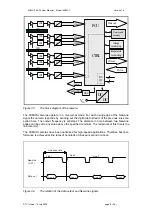
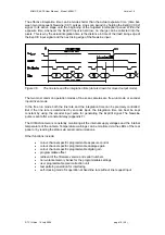
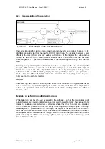
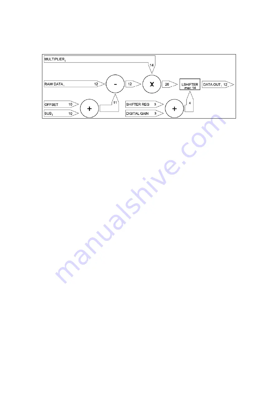
Figure 4.3.
Block diagram of the correction data path.
The correction algorithm is implemented as illustrated above for each colour channel. Firstly,
all offsets are subtracted from the raw 12-bit CCD output data. This includes the pixel to pixel
offsets in the dark (DSNU) and any custom subtractions. In the diagram this subtraction is
marked as SUB
i
. Also, the colour channel specific offset is subtracted from the raw data.
Thus, altogether it is possible to subtract half of the camera dynamic range from the raw
data.
Secondly, after performing the subtractions, the data is multiplied with a 14-bit pixel specific
multiplier. This will result in a maximum of 26 bits of data per pixel, out of which, the topmost
12-bits are routed to the data output of the camera. The output data passes through a left
shifter where it is possible to digitally amplify the data by shifting it zero to seven positions to
the left. Also, the shifter will shift the data to the correct location depending on the unity mul-
tiplier level set in the shifter register.
Example:
The shifter register is set to 7, which equals 128 as a unity multiplier. The digital gains are set
to 7 as well, which equals 128x digital gain. In this case, the result after the multiplication is
shifted up 14 positions which means the lowest 12-bits of the resulting 26-bits are shifted to
the data output.
Example on performing multiple corrections
White balancing can be achieved by selecting the multipliers so that the data values on all
colour channels are equal in digital response from pixel to pixel. Normally, the channel that is
closest to saturation is selected as a reference where the other channels are corrected.
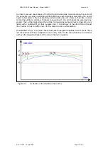
Other choices are possible but they limit the dynamic range of the output signal. The image
below depicts a typical situation. In the image, the output of the red channel is where the
other two channels are corrected. Now, to achieve white balance, the red channel line has to
be multiplied with a constant one for every pixel in the line and the green and blue channel
pixels with multipliers of little over one varying from pixel to pixel, so that each colour pixel will
have a balance of its own.
© TVI Vision, 14 July 2006 page 14 ( 56 )


