


Operator Manual
Issue 1
TIL – Eng – Spec – 080
Page 27 of 70
SeaHub
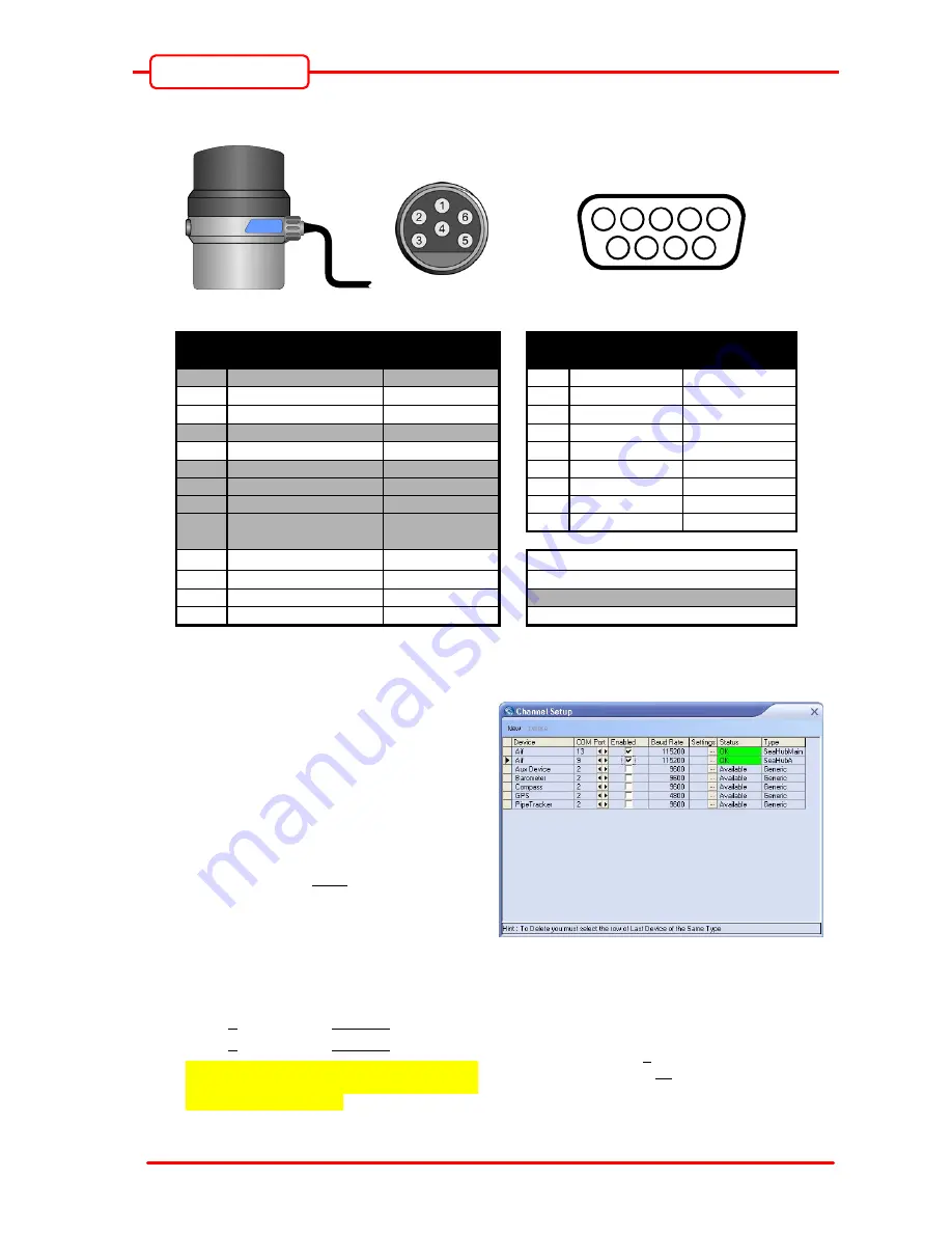
To Ports A or B…
Before connecting please read the notes above.
Connect cable to
Sonar “Main” Port
Micron Connector
(Face View)
1
2
3
4
5
6
7
8
9
SeaHub Port A or B Connector
(Face View)
Pin
Function
Cable Whip
Wire Colour
Pin
RS232 Mode
Function
RS485 Mode
Function
1
No Connection No Connection
1
RS232 Tx/A
Yellow
−
2
RX A
2
RS232 Rx/B
Blue
−
3
TX B
4
No Connection No Connection
4
POWER GROUND
Black
−
5
GROUND GROUND
6
No Connection No Connection
7
No Connection No Connection
8
No Connection No Connection
9
No Connection No Connection
3
POWER POSITIVE
Red
−
SeaHub Red 4mm “Banana” Socket
4
POWER GROUND
Black
−
SeaHub Black 4mm “Banana” Socket
5
No Connection
Green
6
POWER SCREEN
Screen
−
SeaHub Green 4mm “Banana” Socket
To enable Port A or B for a serial Micron connection…
1) Recall the 6 x USB Serial Ports that were
allocated in Device Manager after the
SeaHub was connected and its drivers
installed. Refer to sections 4.2.2 & 4.2.3 on
page 17 onwards.
2) In “Seanet Setup”, click on ‘Utilities’ | ‘Com
Setup’ to open the Channel Setup page
(see right). If there is only 1 x “Aif” device,
add a 2
nd
“Aif” device by clicking on ‘New’
and selecting ‘Aif’. Note: The SeaHub will
need to be connected to its own “Aif”
interface and therefore a 2nd “Aif” interface
is required for the Port A or B connection of
the serial Micron.
3) For the Micron connection, set the COM
Port of the 2
nd
“Aif” device to be;
Port A: COM Port = Base + 0.
Port B: COM Port = Base + 1.
In the Channel Setup table, refer to the
‘Type’ column for SeaHub Port description,
i.e. “SeaHubA” = Port A.
i.e. In previous example (see Section 4.2.2), the
SeaHub was installed with 6 x Serial Ports from
COM 9 to 14.
Therefore;
For Port A, Base + 0 = 9.
For SeaHub, Base + 4 = 13.


