


69
(11) Control System’s
PID Control
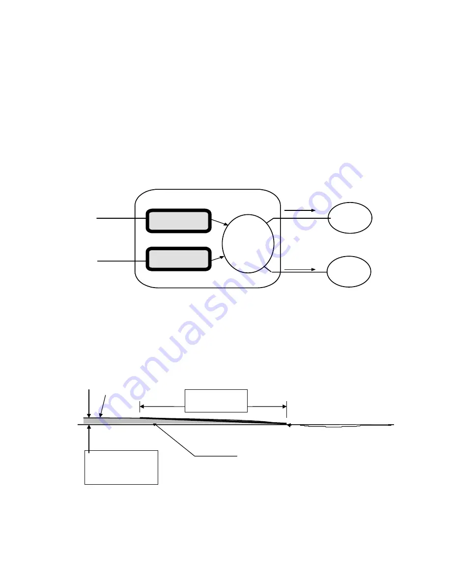
The simplified control (Figure 19) illustrates how the
microprocessor uses two temperature inputs to manage
AFD solution speed control and energy input. The PID
generated by these inputs can be modified by limit
functions before the final output signals are transmitted to
the respective control devices. The chiller module
determines when and how the output signals are
transmitted.
Gain, Reset and derivative settings are available at the CLD
in the service setting (service level inputs). Factory tested
settings are intended to provide satisfactory performance
under most site conditions, however, these inputs are
accessible for those occasions when it is necessary to make
field adjustments.
Figure 19. Simplified diagram of leaving water temperature
control and concentration control
1) Leaving
Water
Temperature
Input
2) Conc
Input
Control System
Leaving Water
Temperature PID
Conc. PID
Limit
Control
AFD
Control
Energy
Control
An input from Leaving Water Temperature or Conc. control
must first pass through PID control and second limit control
before reaching the output device. The microprocessor first
performs the PID functions of the control to determine what
control correction signal is required, and second,
determines if that signal is allowable by safeties or limit
schedules condition.
Figure 20. Identifies the PID functions.
Actual temperature
Rate of change =
Derivitive (D)
Area under curve =
Integral (I)
Setpoint
amount away from
setpoint = Proportional
(P)
Gain = P, Reset = P/I, D = derivative
The PID functions look at the actual temperature verses
setpoint, evaluates the distance away from the setpoint (P),
the length of time away from setpoint (I), and the rate of
change away or towards the setpoint (D).