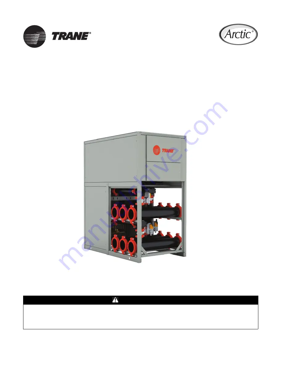
background image

December 2021

ARTC-SVX005B-EN

SAFETY WARNING

Only qualified personnel should install and service the equipment. The installation, starting up, and servicing of 
heating, ventilating, and air-conditioning equipment can be hazardous and requires specific knowledge and training. 
Improperly installed, adjusted or altered equipment by an unqualified person could result in death or serious injury. 
When working on the equipment, observe all precautions in the literature and on the tags, stickers, and labels that are 
attached to the equipment.

PolyTherm™
Simultaneous Chiller/Heater

Installation, Operation, and Maintenance

Summary of Contents for Arctic PolyTherm TM Series

Page 1: ...pment can be hazardous and requires specific knowledge and training Improperly installed adjusted or altered equipment by an unqualified person could result in death or serious injury When working on the equipment observe all precautions in the literature and on the tags stickers and labels that are attached to the equipment PolyTherm Simultaneous Chiller Heater Installation Operation and Maintena...

Page 2: ...ar r p pr ro op pe er r P PP PE E f fo or r t th he e j jo ob b b be ei in ng g u un nd de er rt ta ak ke en n c co ou ul ld d r re es su ul lt t i in n d de ea at th h o or r s se er ri io ou us s i in nj ju ur ry y T Te ec ch hn ni ic ci ia an ns s i in n o or rd de er r t to o p pr ro ot te ec ct t t th he em ms se el lv ve es s f fr ro om m p po ot te en nt ti ia al l e el le ec ct tr ri ic ca...

Page 3: ...dl li in ng g e et tc c W Wh he er re e l lo oc ca al l r re eg gu ul la at ti io on ns s a ar re e m mo or re e s st tr ri in ng ge en nt t t th ha an n t th he es se e p po ol li ic ci ie es s t th ho os se e r re eg gu ul la at ti io on ns s s su up pe er rs se ed de e t th he es se e p po ol li ic ci ie es s N No on n T Tr ra an ne e p pe er rs so on nn ne el l s sh ho ou ul ld d a al lw wa ay...

Page 4: ... Couplings 22 Installation Electrical 23 Wiring and Piping 23 Connecting Module Power and Control Wires 23 Service Access 23 Chiller Heater Module Main Power 23 Module Control Wiring 23 Phase Monitor Installation 23 Power Interlock Switch 24 Operating Principles 25 Operating Procedures 27 Operator Interface 27 Chiller Heater Power Panels 27 Panel Mounted Disconnect Switch 27 Power Distribution Pan...

Page 5: ...y Guidelines 48 Monitor Water Quality 48 Maintain Glycol Level 49 Prevent Freezing 49 Controls Interface 51 Chiller Controls 51 Power Distribution 51 Touchscreen Interface Panel 53 Microprocessor Control System 53 Primary Microprocessor Controller 53 Secondary Microprocessor Controller 53 Microprocessor Controller Functions 53 Thermal Capacity 54 Electronic Controls 54 Sequence of Operations 55 De...

Page 6: ...ow 71 Water Glycol Mixture Logical Flow 73 Acronyms and Abbreviations A 1 Acronym List A 1 Request for Initial Startup B 1 PolyTherm Chiller Heater B 1 Initial Startup Agreement B 1 Active Alarm List C 1 Application C 1 Alarm List C 1 T Ta ab bl le e o of f C Co on nt te en nt ts s ...

Page 7: ...dent Refrigeration Circuits S Single Refrigeration Circuit R Redundant Refrigeration T Tandem Compressors Set in Single Circuit Digit 13 Voltage 1 208 230 60 1 2 460 60 1 3 208 230 60 3 4 460 60 3 5 575 60 3 7 380 50 3 Digit 14 15 Chiller Application MM Modular CP Cold Plunge Process DW Drinking Water and Filtration Digit 16 17 Configuration 1 DS Digital Scroll DS1 Digital Scroll Lead Compressor D...

Page 8: ... table below Chiller Reference Data Refer to the Trane nameplate on each module in the installed unit for the serial number and model number See figure below for example nameplate Table 1 Chiller Heater reference data Module Model Number Serial Number 1 2 3 4 5 6 7 8 9 10 Figure 1 Typical PolyTherm chiller heater nameplate Model Coding Key Model numbers assigned to Trane systems provide a wealth o...

Page 9: ...diate joint inspection by the carrier and consignee A determination of responsibility will be made and the carrier will authorize repairs in the event of admission of fault 7 Notify Trane customer service department 803 321 1891 immediately Trane will coordinate repairs with the owner and carrier Do not attempt to make repairs locally without permission Warranty Issues Trane is not responsible for...

Page 10: ...t t u us se e t th he e p pr ro od du uc ct t f fo or r l li if fe e o or r s sa af fe et ty y a ap pp pl li ic ca at ti io on ns s D Do o n no ot t e ex xc ce ee ed d t th he e p pr ro od du uc ct t r ra at ti in ng gs s o or r m ma ax xi im mu um m l li im mi it ts s P Pr ro od du uc ct ts s r ra at te ed d o on nl ly y f fo or r b ba as si ic c i in ns su ul la at ti io on n m mu us st t b be e...

Page 11: ...304 B 81 1 16 81 1 16 81 1 16 81 1 16 81 1 16 81 1 16 81 1 16 81 1 16 81 1 16 81 1 16 C 13 13 13 13 13 13 13 13 13 13 D 65 7 8 65 7 8 65 7 8 65 7 8 65 7 8 65 7 8 65 7 8 65 7 8 65 7 8 65 7 8 LBS 1 400 2 800 4 200 5 600 7 000 8 400 9 800 11 200 12 600 14 000 40 Ton PolyTherm A 34 68 102 136 170 204 238 272 306 304 B 81 1 16 81 1 16 81 1 16 81 1 16 81 1 16 81 1 16 81 1 16 81 1 16 81 1 16 81 1 16 C 13...

Page 12: ...of 4 inch wide preferably 6 inch wide and seated on springs pads Custom modules may have different requirements Consult submittal drawings to confirm dimensions After setting and lubricating the mounting rails begin installing the modules All of the modules arrive with labels on the electrical and control panel Review the installation drawings to determine which is the first primary module Typical...

Page 13: ...ft and move by strapping and lifting by overhead means Position lifting beams or spreader beams to prevent lifting straps from rubbing or contacting module side panels or electrical boxes Attach rigging bar on each end of module where 1 3 8 inch holes are provided Use caution when lifting due to configuration of components Module could be heavier on one side than the other Certain configurations o...

Page 14: ...ri if fy y t th ha at t n no o p po ow we er r i is s p pr re es se en nt t w wi it th h a a v vo ol lt tm me et te er r The water source modular simultaneous heating and cooling system consists of individual modules that are assembled on site Each PolyTherm module is factory wired and tested prior to shipment Each module includes a compressor a brazed plate evaporator a brazed plate condenser a s...

Page 15: ...between each plate The filler material forms a brazed joint at every contact point on the plates creating complex channels This allows fluid to come into close proximity separated only by channel plates that enable heat from one fluid to be transferred to the other with very high efficiency but without gaskets and frame parts Models with the brazed plate heat exchanger are made of SAE Grade 316 st...

Page 16: ...tion to prevent condensation and retain heat and cold Each heat recovery module is connected to the adjacent module using roll grooved steel couplings and neoprene gaskets on all joints Electronic Expansion Valve An expansion valve is a metering device controlling the flow of refrigerant to the evaporator based on evaporator superheat The electronic expansion valve is designed to act as the expans...

Page 17: ...e into an electronic signal that the microprocessor displays in pounds per square inch psi Transducers vary in pressure ranges that depend on the type of refrigerant used Pressure transducers are calibrated using the touchscreen interface panel Temperature sensors transmit temperature data electronically to the microprocessor for display in either Fahrenheit F or Celsius C Temperature sensors are ...

Page 18: ... pumps as described previously Bump pump motors on to verify correct rotation 7 Inspect all refrigerant pressures for each module to ensure no refrigerant has been lost 8 Check that pressure switches and thermostats have correct cut in and cut out settings 9 Confirm the oil level is correct in each compressor N NO OT TI IC CE E C Co om mp pr re es ss so or r F Fa ai il lu ur re e F Fa ai il lu ur ...

Page 19: ...age 3 ___________________ Check the box if there are any field supplied wiring junction boxes located between the chiller heater and any remote panels Check the box if there are any splices made in the field supplied wiring junction boxes Check the box if there are any customer supplied devices connected to the chiller heater wiring List devices ____________________________________________________...

Page 20: ... Check the box if all water refrigeration electrical and control connections between chiller heater modules are completed Check the box if all control wiring between modular chiller heaters is installed tested and functional Check the box if control wiring is complete including any remote interface panel or special purpose module wiring Check the box if all responsible installing contractors and s...

Page 21: ...tion deposited during fabrication of the piping system Typical flushing includes hot water with mild detergent followed by a dilute phosphoric acid solution until all visible residue is removed Only cleaning liquids acids and detergents compatible with SAE Grade 316 stainless steel copper and carbon steel should be used Consult a professional water treatment specialist when in doubt Flushing shoul...

Page 22: ...e headers 4 Lubricate the main header coupling gasket with an approved lubricant and re install onto the roll grooved header pipe Push the gasket flush with the pipe end to avoid damage when installing the next module 5 Remove the small coupling that attaches the main header to the heat exchanger 6 After positioning the module slide the header and rotate it to avoid damage to the refrigeration pip...

Page 23: ...national codes An earth ground lug is provided on the cabinet exterior for proper grounding according to national electrical codes An earth ground is necessary to ensure personnel safety to prevent electrical hazards around this equipment Read and follow installation instructions for proper operation This unit is equipped with a flow switch The chiller heater will not run unless the pump is circul...

Page 24: ...co on nn ne ec ct t a al ll l e el le ec ct tr ri ic c p po ow we er r i in nc cl lu ud di in ng g r re em mo ot te e d di is sc co on nn ne ec ct ts s b be ef fo or re e s se er rv vi ic ci in ng g F Fo ol ll lo ow w p pr ro op pe er r l lo oc ck ko ou ut t t ta ag go ou ut t p pr ro oc ce ed du ur re es s t to o e en ns su ur re e t th he e p po ow we er r c ca an n n no ot t b be e i in na ad d...

Page 25: ...igure 7 PolyTherm simultaneous chiller heater The PolyTherm Chiller Heater is designed to operate with a water glycol mixture to prevent rust scaling and organic growth and uses R 410A or R 134a refrigerant The simultaneous heating and cooling system is designed to operate in heating mode cooling mode or simultaneous heating and cooling based on the system demand by opening and closing electronic ...

Page 26: ...nger as refrigerant has been redirected such that it operates as an evaporator Figure 9 50 and 60 tons PolyTherm dimensions In simultaneous heating and cooling mode the diverting valves direct the load heating fluid to the condenser and the load cooling fluid to the evaporator Electronic valves on the brazed plate source sink heat exchanger outlet modulate to control refrigeration head pressure El...

Page 27: ...ower to the individual electrical components in that module Panel Mounted Disconnect Switch SomePolyTherm Chiller Heater systems are optionally equipped with a panel mounted disconnect switch installed on the outside of the power distribution panel or on each module s electrical and control panel if the chiller heater has power supplied to each individual module The disconnect switch must be turne...

Page 28: ...an electronic expansion valve controller and low power terminal blocks See Figure 12 p 28 Electronic Control PolyTherm Chiller Heater models use electronic controllers to monitor and report critical operating parameters The module uses a microprocessor controller located in the module control panel See Figure 12 p 28 and Figure 13 p 29 Figure 12 Module control panel Controller Relay Expansion Boar...

Page 29: ...rocessor control programming only lacks the ability to rotate the lead compressors which typically occurs every 168 compressor operating hours In a normal configuration a secondary controller controls the single module to which it is dedicated The secondary controller monitors key performance parameters for its module and sends real time information to the primary controller The primary controller...

Page 30: ...y a host of functions involving temperatures pressures set points alarms operating schedules and elapsed operating hours This touchscreen interface panel is typically located on the exterior door of the power distribution panel The touchscreen interface is connected to and communicates with all module controllers via the Ethernet switch It accesses overall chiller heater functions and settings as ...

Page 31: ...geration circuit heat exchangers compressors and the module itself There are two overview screens for each module These screens are different for the primary module and the secondary modules Input Output Screen The state and description of the module microprocessor controller s digital and analog inputs and outputs The I O menu is comprised of four screens for primary module and three screens for ...

Page 32: ... a list of currently active system alarms The date time displays the current settings of the system isochronon Home Screen The home screen button appears on every screen for fast display of the home screen from any screen in the interface Module The module access buttons display the overview screen for each module These buttons provide access all chiller heater modules screens individually The num...

Page 33: ...urth number indicates the beta software revision sequence Middle Section Functions Chiller Status Features in the middle section include status indicators and controls for the chiller heater system as a whole Chiller heater temperature set points for cooling and heating Chiller heater system cooling in and out water temperatures Chiller heater system heating in and out water temperatures Chiller h...

Page 34: ...ccess level password is entered for the tech and admin levels There is no name or password required for the user access level Pressing the sign in button automatically logs the operator into the user access level See the following figure Figure 19 User logging screen Current Access Level This item indicates which access level is currently logged in There are three access levels for the PolyTherm i...

Page 35: ...tech level to the default user level Modules Layout Screen The chiller heater can be composed of up to a maximum of ten modules Pressing the Layout button displays the screen showing the status of compressors and valves in each module See the following figure Each module diagram is a set of symbols and colors that show the real time status of the compressors the refrigeration circuit the isolation...

Page 36: ...ED is gray valve is closed Refrigeration circuit in normal state both compressors on Refrigeration circuit in alarm state compressors off Modules Overview Screens Each module controlled by the microprocessor controller has its own module screen within which the operator can monitor and maintain conditions affecting that module Primary module access is made through the system control screen contain...

Page 37: ...on for both heating and cooling loads It also acts as a supervisor when communicating with the secondary modules and defines how many modules need to run compressors in order to satisfy heating and cooling loads N No ot te e Primary Module is defined by its PLC IP address So in the chiller primary PLC IP address is always 192 168 1 11 All secondary IP addresses go from 192 168 1 12 to 192 to 192 1...

Page 38: ...le when Its microprocessor controller has been assigned the IP address from the secondary address range It is communicating with primary module The primary module exists on the network The primary microprocessor controller meets primary module conditions Mode Status There are six possible values S Si im mu ul lt ta an ne eo ou us s The module is in simultaneous mode H He ea at ti in ng g The modul...

Page 39: ...ing and cycling through safety Minimum On Time S St ta ar rt t D De el la ay ye ed d First Compressor waiting for EXV to open to preset position 70 by default Second Compressor cycling through Compressor Staging Delay O OF FF F b by y S SS ST T The second compressor is off by too low Saturated Suction Temperature O OF FF F b by y S SD DT T The second compressor is off by too high Saturated Dischar...

Page 40: ...I O button displays the I O menu The I O menu is comprised of four screens for primary module and three screens for secondary module Both primary and secondary modules have Analog I O analog input and analog output Digital I O digital input and digital output and Expansion 2 I O screens The fourth screen Expansion 1 I O applies to primary module only Table 9 The input output screens Primary I O An...

Page 41: ... for each of the three heat exchangers evaporator condenser or source AI4 This input indicates suction pressure AI5 This input indicates discharge pressure AI9 This input indicates the panel temperature optional It is used when the temperature control inside the control panel requires either heating for a cold environment or cooling for a hot environment Analog Outputs Analog output AO data includ...

Page 42: ...ing normal range threshold that is faulty state DI9 Phase Monitor This is feedback for the three phase power supply protection feature If the digital input for this switch indicates closed there are no power supply issues If the digital input for this switch indicates open a power supply failure has been detected If the primary phase monitor is enabled the common power supply protection module is ...

Page 43: ...D2 S1 S2 Active Alarms Screen Figure 22 Active alarms for the chiller heater The active alarms screen lists all active triggered and non active alarms in tabular form See following figure Information presented in this screen in tabular form includes Select This column indicates if the alarm is selected or unselected for acknowledgment or resetting Action This column brings up more details upon tap...

Page 44: ...e active alarms list Save Pressing this button saves the changes made to the active alarms list Any changes that are made without saving will be lost Reset PLC This button located in the upper right portion of the screen resets the active alarms in the primary microprocessor so they could be further acknowledged or reset on the touchscreen interface Only those alarms for which the alarm condition ...

Page 45: ...the list and the From and To timestamps will update accordingly Time This is the time stamp that is displayed when the alarm state changes Status This is the same as Status for active alarms State This is the same as State for active alarms Trend Screen When on the primary module screen pressing the trend button displays the trend screen There are two trend screens cooling trend screen and heating...

Page 46: ...ending variables instantaneous values according to cursor position Current cursor time stamp is displayed as well This is the drop down text box used to select the trending time span It is used to for focusing on a specific time period Options available for selection include Figure 25 Time span selection options menu O Op pe er ra at ti in ng g P Pr ro oc ce ed du ur re es s ...

Page 47: ...e es su ul lt t i in n d de ea at th h o or r s se er ri io ou us s i in nj ju ur ry y D Di is sc co on nn ne ec ct t a al ll l e el le ec ct tr ri ic c p po ow we er r i in nc cl lu ud di in ng g r re em mo ot te e d di is sc co on nn ne ec ct ts s a an nd d d di is sc ch ha ar rg ge e a al ll l m mo ot to or r s st ta ar rt t r ru un n c ca ap pa ac ci it to or rs s b be ef fo or re e s se er rv...

Page 48: ...single module It does not cut power to electrical and control panel or other chiller heater modules Press the SYSTEM ON button on the touchscreen interface panel that is built into the power distribution panel door N No ot te e Pressing the SYSTEM ON button on the touchscreen interface panel does not de energize the chiller or the high voltage current into each module s electrical and control pane...

Page 49: ...T TI IC CE E E Eq qu ui ip pm me en nt t D Da am ma ag ge e F Fa ai il lu ur re e t to o f fo ol ll lo ow w i in ns st tr ru uc ct ti io on ns s b be el lo ow w c co ou ul ld d r re es su ul lt t i in n p pe er rm ma an ne en nt t d da am ma ag ge e t to o p pu um mp p a an nd d i in nt te er rn na al l c co oo ol li in ng g s su ur rf fa ac ce es s D Do o n no ot t u us se e a au ut to om mo ot t...

Page 50: ...ure falls the slush becomes more and more viscous and finally fails to flow The calculations in this table are most accurate for Dowfrost propylene glycol and Dowtherm ethylene glycol branded products Consult your local supplier or engineering contractor for more precise recommendations The precise concentration of glycol for a particular chiller heater is affected by several key factors such as a...

Page 51: ...The main power distribution panel receives power from the building source and distributes it to the individual modules The module electrical and control panel receives power from the power distribution panel and provides power to individual electrical components W WA AR RN NI IN NG G H Ha az za ar rd do ou us s V Vo ol lt ta ag ge e F Fa ai il lu ur re e t to o d di is sc co on nn ne ec ct t p po ...

Page 52: ...trol panel if the chiller heater has power supplied directly to each individual module The disconnect switch must be turned to the off position before the panel can be opened for service Module Electrical Panel From the power distribution panel power is fed to the individual modules in the chiller heater and connects to each module s electrical panel See the following figures Figure 30 PolyTherm p...

Page 53: ...ler rotates the lead compressors every 168 system operating hours The primary controller reads all analog and fault port values from the secondary controllers and passes these values to the Building Automation System BAS This controller must have the optional BAS card installed to connect to a building automation system Figure 33 PolyTherm chiller heater controller Secondary Microprocessor Control...

Page 54: ...ious 1 000 alarms Remote start stop input Dry contact for general alarm Thermal Capacity The thermal capacity of the chiller heater modules is dependent on the leaving temperature of the chilled water glycol mixture maintaining a minimum flow of water through the heat exchangers In applications where it is desired to operate with a lower flow rate or higher temperature change consult Trane technic...

Page 55: ...mode cooling mode or simultaneous heating and cooling based on the system demand by opening and closing electronic diverting valves on the evaporators condensers and source sink heat exchanger When in cooling mode the diverting valves direct the load chilled fluid to the evaporator and simultaneously direct the source sink fluid to the brazed plate heat exchanger operating as a condenser When in h...

Page 56: ...F 7 C EFT 65 F 18 C LFT 77 F 25 C Flow Rate 600 gpm Flow Rate 650 gpm Pressure Drop 3 8 psi Pressure Drop 4 2 psi Cooling Capacity 3 480 000 btu hr 290 tons Heating Mode Load Source Sink Heat Exchanger EFT 100 F 38 C LFT 120 F 49 C EFT 60 F 16 C LFT 50 F 10 C Flow Rate 300 gpm Flow Rate 424 gpm Pressure Drop 1 6 psi Pressure Drop 2 4 psi Cooling Capacity 2 968 000 Btu hr 870 kW Simultaneous Heatin...

Page 57: ...eekly or monthly periodic maintenance involves cleaning specific components and inspecting glycol and lubrication fluids Finally since all components will eventually wear out a prudent maintenance strategy will anticipate and schedule replacement or rebuilding of critical components before they fail and require emergency response to keep chillers operational See below figure Maintenance for HVAC e...

Page 58: ...asures should be taken to prevent potential problems with the chillers These include maintaining a operational log and conducting weekly quarterly and annual inspections of the chiller heater See following table Daily A daily visual inspection can reveal obvious problems Keep notes of the chiller performance Log pressures and temperatures Visually inspect of the unit Check for noises as well as oi...

Page 59: ...e em mo ov ve e m mo oi is st tu ur re e 4 When the compressor is not operating the oil level should be at least at the bottom of the sight glass up to two thirds full When the compressor is operating the oil level will normally be at the bottom of the sight glass or even below but it must be visible 5 Low oil sight glass conditions could signify an undercharged chiller that lacks proper refrigera...

Page 60: ...ant leaks Inspect all pressure switch bellows 10 Tighten all refrigeration piping connections e g rotalocks stems and packing nuts Schrader valves and ball valves 11 Install a manifold and gauge set to observe chiller heater s refrigeration operating pressures a Verify that the pressure controls low pressure and high pressure switches are cutting in and cutting out at the appropriate pressures b V...

Page 61: ... The maintenance tasks described herein present the basic minimal steps required to successfully complete a task Local policies and protocols may require more elaborate procedures with additional checks and inspections Freely substitute in those cases where local procedures are more elaborate and complete than the procedures listed in this manual Compressors filter strainers and liquid line shutof...

Page 62: ... th he e e en nd d c ca ap p a an nd d r re el le ea as se e p pr re es ss su ur re e g gr ra ad du ua al ll ly y 4 Inspect the gasket and service cap for abrasions tears excessive dirt or deterioration Replace gasket if necessary 5 Remove the strainer from the housing 6 Clean the strainer inside and out using a soft natural bristle brush and tap water 7 Clean the interior of the end cap or servic...

Page 63: ...ce as the compressors are moved 10 Remove the compressors from the module by lifting or sliding Install Tandem Compressor Verify that power is disconnected from the chiller heater W WA AR RN NI IN NG G H Ha az za ar rd do ou us s V Vo ol lt ta ag ge e F Fa ai il lu ur re e t to o d di is sc co on nn ne ec ct t p po ow we er r b be ef fo or re e s se er rv vi ic ci in ng g c co ou ul ld d r re es s...

Page 64: ...e will flash yellow two times when the compressor operates from 12 seconds to 15 minutes followed by a trip condition lasting longer than 7 minutes When four consecutive or ten total CODE 2 events are recorded the module will lockout the compressor and flash red two times C CO OD DE E 3 3 Pressure Switch Cycling The module will flash yellow three times when the compressor operates from 12 seconds ...

Page 65: ...DE 8 Yellow Flash 8 Welded contactor Module has detected line currents in R and S windings and Y or Y1 is at 0 Vac for 15 seconds N A N A CODE 9 Yellow Flash 9 Low voltage Module has detected a 24 Vac supply voltage below 17 Vac 1 Vac for 2 seconds N A N A CODE 10 Red Flash 10 Over current protection PROT terminal has above a 2A input for more than 40 milliseconds 1 occurrence Red Flash 10 Phase M...

Page 66: ... or low refrigerant charge No high voltage power to contactor Check breakers energize from power distribution panel and module electrical panel check ON OFF button in touchscreen interface Phase monitor open or tripped Over or under 4 to 8 loss of leg 2 Symptom Compressor will not run Possible Causes Potential Solutions Compressor not powered Assure all circuit breakers are in the ON position Circ...

Page 67: ...ning Increase suction pressure suction temperature pressure check for proper superheat check electronic expansion valve replace if necessary cabling to stepping motor contact Trane technical support Compressor service valves closed Open service valve if so equipped counterclockwise completely Clogged liquid line filter drier Replace liquid line filter drier or core Excessive glycol concentration D...

Page 68: ...ainer check pump and differential pressure settings System controls malfunctioning Check and replace temperature sensors if necessary 11 Symptom High chilled water temperature Possible Causes Potential Solutions Refrigeration circuits not cooling Check electronic expansion valve for excessive flow adjust or replace electronic expansion valve Load higher than capacity of chiller heater Refer to chi...

Page 69: ...ructed filter dryer Replace filter dryer Low refrigerant charge Adjust refrigerant as per data plate Improperly set superheat valve setting Reset valve settings to factory specifications 16 Symptom Electronic expansion valve superheat too low Possible Causes Potential Solutions Suction temperature sensor not properly located Check if secured to pipe or insulated check sensor position on pipe at 4 ...

Page 70: ...y inoperative Possible Causes Potential Solutions Low water flow Remove restrictions increase flow clean strainer Low suction pressure See low suction pressure C Ch hi il ll le er r H He ea at te er r T Tr ro ou ub bl le es sh ho oo ot ti in ng g ...

Page 71: ...worldwide market The high voltage configuration for a chiller heater module is listed on each module s name plate The chiller heater is designed to operate with high voltage power supplied to the unit at all times Control Logical Flow The chiller heater uses low voltage for controller and sensor circuits See following figure Figure 36 PolyTherm chiller heater control wiring primary module ...

Page 72: ...72 ARTC SVX005B EN Figure 37 Expansion board wiring primary module Figure 38 Expansion valve wiring L Lo og gi ic ca al l F Fl lo ow w ...

Page 73: ...e recommends using a water glycol mixture instead of an all water fluid The water glycol mixture is used within a closed system as shown in the following figure Figure 39 PolyTherm chiller heater piping installation diagram L Lo og gi ic ca al l F Fl lo ow w ...

Page 74: ...opean ckt circuit CL cool Cntrl Contrl Controller Comm Communication Comp Comps Compressor Compressors CoolDemand Cooling Demand Table 17 Acronyms and abbreviations continued Item Expansion Compens Compensation COND Cond condenser CSA Canadian Standards Association CSV Comma Separated Values DB Dry Bulb DB Distribution Block DifPr Differential Pressure Dis Disabled Dish Discharge Disturb Distribut...

Page 75: ...LPS Low Pressure Switch LRA Locked Rotor Amperes m minute Table 17 Acronyms and abbreviations continued Item Expansion Max Maximum Mem Memory Min Minimum MON Monday ms millisecond Mx Module 1 through x NEMA National Electrical Manufacturers Association NFPA National Fire Protection Association NTC Negative Temperature Coefficient Num Number OA Outside Ambient OAT Outside ambient Air Temperature OD...

Page 76: ...ing Water Temperature SysHotLWT System Hot Leaving Water Temperature Temp Temperature Table 17 Acronyms and abbreviations continued Item Expansion Temp Diff Temperature Differential minus Temp Diff Temperature Differential plus TEMPS Temperatures THU Thursday TT Twin Turbine TUE Tuesday TXV Thermal Expansion Valve U1 U2 binary 1 binary 2 UL Underwriters Laboratories UV Ultraviolet VAC Volts Altern...

Page 77: ...es from chiller to customer s equipment are permanently connected Chilled water lines have been flushed clean of mud slag and other construction debris All chilled water line filters and strainers are clean Chilled water lines have been leak tested according to prestart instructions Chiller reservoir if included is at operating level with correct water glycol mixture High voltage wiring is install...

Page 78: ...orted initial startup Name Printed ____________________________________ Date ______________________________________ Signature _________________________________________ Company __________________________________ R Re eq qu ue es st t f fo or r I In ni it ti ia al l S St ta ar rt tu up p ...

Page 79: ...ating temperature control sensor If the LWT is selected as the cooling or heating temperature control sensor If the EWT is selected as cooling or heating temperature control sensor and the module is running in stand alone mode If the LWT is selected as cooling or heating temperature control sensor and the module is running in stand alone mode If both compressors are in lock out that will in turn l...

Page 80: ...ry Auto Reset Shuts down local heating control UI4 SENSOR FAILURE Primary Secondary Auto Reset Shuts down module if LP Alarm Mode Sensor UI5 SENSOR FAILURE Primary Secondary Auto Reset Shuts down module UI6 SENSOR FAILURE Primary Secondary Auto Reset Shuts down local heating control UI7 SENSOR FAILURE Primary Secondary Auto Reset Warning UI8 SENSOR FAILURE Primary Secondary Auto Reset Locks out mo...

Page 81: ... NUMBER OF RETAIN MEMORY WRITINGS Primary Secondary Operator Reset Warning ERROR in RETAIN MEMORY WRITINGS Primary Secondary Operator Reset Warning WRONG TEMPERATURE CONTROL PARAMETERS Primary Secondary Auto Reset Warning WRONG LOCAL ROTATION CONTROL PARAMETERS Primary Secondary Auto Reset Warning PRIMARY COMMUNICATION LOST Secondary Auto Reset Switches secondary module to stand alone mode INCOMPL...

Page 82: ...82 ARTC SVX005B EN N No ot te es s ...

Page 83: ...ARTC SVX005B EN 83 N No ot te es s ...

Page 84: ...ates comfortable energy efficient indoor environments for commercial applications For more information please visit trane com or americanstandardair com Arctic designs cost efficient leading edge chillers and applied solutions to meet individual customer needs from large medium to smaller scale systems For more information please visit www arcticchillergroup com ARTC SVX005B EN 15 Dec 2021 Superse...

Reviews: