tousek ST 80 Installation And Connection Manual Download Page 12

- 12 - 

tousek

  /  EN_ST-80-M-S_05  /  25. 03. 2020

Safety


Connections and adjustments

 Important

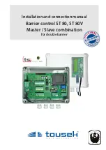
•  Jumper J of  transmitter and receiver has to 

be adjusted in the same way.


Photocell Tousek LS 26  


as safety device

+~

-~

12/24V

J

+~

-~

12/24V

NC C NO

J

transmitter receiver

41

42

43

44

45

46

Photocell - connection examples 

M


G

 Photocell 

(contact: terminals 

M

  45/46)  

M


Safety


active: 

to be selected, if photocell should be triggered. 


not active:  

to be selected, if photocell should not be triggered.

                                           Important: Photocells notes


M

Photocell connection at Master control unit:

•  the control unit has a power supply connection for a 

24V a.c.

 photocell (PHC)

  power supply:

 PHC-transmitterr:  term.


M

 41/42    

Note:  in „gate closed“ position the terminals 41/42 

are being switched into energy saving mode (no 

current) !


PHC-receive: 

term.


M

 43/44 

• 

The PHC contacts have to be closed when using powered and positioned photocells (opening contact).


PHC-contact:

 terminals


M

 45/46

Mounting note (SYNC function):

 IMPORTANT:

 When  using  two  pairs  of  photocells  please  do  not  

install  both  photocell  transmitters/receivers on the same side (to 

eleminate interference between both) !

 Exception:

 photocells with SYNC function allow the installation of 

both photocell transmitters/receivers on the same side without causing  

interference to each other.

Self-monitoring of photocells: 


The control unit has a monitoring function for the connected photocells. A test will be triggered by each impulse 

and will be checked if the receiver of the photocell responds to the signal from the photocell transmitter. If the-

re is no communication between the photocell receiver and transmitter the control unit responds with an error.  


The deactivation of the self-test function is only permitted if the safety installations correspond to the  

category 3 !

Photocell function: 

  The exact function of the photocells depend on the programming of the control unit: 


see menu point SAFETY / PHC/ISD function and SAFETY / PHC/ISD pause time (

 page 14).

you will find detailed information in the corresponding photocell manual..

standard

transmitter1 receiver1

receiver2 transmitter2

with SYNC

transmitter1 receiver1

transmitter2 receiver2

Summary of Contents for ST 80

Page 1: ...Installation and connection manual Barrier control ST 80 ST 80V Master Slave combination for double barrier...

Page 2: ...he manual replaces all earlier publications of the same Index General warning and safety details 3 1 Notes general characteristics control board layout technical data 4 5 2 Terminal assignment 5 7 3 P...

Page 3: ...They may be hazardous to children and therefore have to be stored out of children s reach The product is not suitable for installation in explosion hazardous areas The product may only be used in acc...

Page 4: ...mmingwithilluminatedLCdisplayinenglischlanguage Three operating modes impulse automatic deadman Automatic closing with adjustable pause time Runtime of operator is being automatically determined Separ...

Page 5: ...plosion hazardousareas An all pole disconnecting mains switch with a contact opening gap of min 3 mm has to be foreseen The barrier facility has to be secured according to the valid safety regulations...

Page 6: ...ns switch with a contact opening gap of min 3 mm has to be foreseen The barrier facility has to be secured according to the valid safety regulations IMPORTANT The control lines sensor buttons radio ph...

Page 7: ...l with slave control the terminals 88 and 89 of system plugs of each control have to be connected with each other see picture below Important max cable length between the barrier housings is 25m Cable...

Page 8: ...the shown value of a parameter is given When pressing the button you return to the superior menu point Possibly changed adjustments of a parameter are rejected with this button the former values will...

Page 9: ...with pause time extension M motor partial opening Master Slave M G operating mode impulse mode automatic 1 255s increment 1 M pause time logic no influence constant open in automatic mode M forced clo...

Page 10: ...r boom stops If deadman mode is selected the radio receiver is set out of order for safety reasons If the impulse switch is set to DEAD MAN operation then the partial opening switch works the same way...

Page 11: ...Note if the function open under menu point is selected and if the impulse switch is set to DEADMAN then the opening of the boom is omitted when driving over the I loop 9 1 9 2 9 3 9 4 I loop 1 I loop...

Page 12: ...two pairs of photocells please do not install both photocell transmitters receivers on the same side to eleminate interference between both Exception photocells with SYNC function allow the installati...

Page 13: ...J 2 photocells Tousek LS 41 LS 180 as safety device with SYNC function activated N O COM N C J J N O COM N C transmitter 1 receiver 1 transmitter 2 receiver 2 41 42 43 44 45 46 SYNC J Important As the...

Page 14: ...sing command has to be actuated Stop during closing then close an interruption of the photocell beam or induction loop during closing makes the motor stop as long as the photocell loop stays interrupt...

Page 15: ...barrier G Operating mode M Operating logic Impulse mode Impulse through impulse switch button or CLOSE button to start closing of barrier Automatic mode pause time 1 255s adjustable increment 1 barri...

Page 16: ...rd the setting is made via Master control Prewarning OPEN signal lamp terminals M S 10 11 M Light lamps turned off 1 30s adjustable Before each opening movement the signal lamp flashing light is activ...

Page 17: ...ay attention to polarity 70 71 74 75 9 1 9 2 9 3 9 4 78 79 R Magnet fix 24V Signal contacts M Peripherals Status display 1 with the two potential free signal contacts K1 and K2 the adjustments of the...

Page 18: ...are newly set after an impulse Software version control function M S Reset Diagnosis shows the software version on display Serial number control function M S Reset Diagnosis shows the serial number o...

Page 19: ...can be made easily with the rotary switches D1 for channel 1 and D2 for channel 2 as well a s the DIP switches DIP see corresponding manual Factory settings DIP1 DIP8 OFF D1 and D2 4 DIP DIP switch RE...

Page 20: ...eiver please see manual for radio receiver Turn off power supply Open cover of control unit Receiver board E RS433 868 STN1 1 channel or RS433 868 STN2 2 channel into the connection slot FE as shown i...

Page 21: ...aster control Exit using ESC button system tests of the master control are carried out If an error occurs you get into the BASIC SETTINGS again by pressing the ENTER button After the successfull syste...

Page 22: ...utton for 5s from any position in menu Master control M Putting into operation BASIC SETTING of Master control For setting the most important adjustments for initial operation of motor Can be selected...

Page 23: ...gered This would lead to an interruption of the programming process Operation mode Operation mode impulse mode Operation mode aut close 5s Operation mode aut close 10s System test Photocell System tes...

Page 24: ...status dispaly for help Display Low Voltage undervoltage check supply line Display search Master communication problem check connection transmission Display search Slave communication problem check co...

Page 25: ...05 25 03 2020 25 240 195 depth 105 9 Dimensioned drawing of box IP54 Barrier control ST 80 ST 80V Master Slave dimensions in mm We reserve the right to change dimensions and technical specifications w...

Page 26: ...used All shear crush and pinch points of the door system must be protected absolutely In this context we refer to the Machinery Directive and safety regulations and EU standards in their country or as...

Page 27: ......

Page 28: ...Gliwicka 67 Tel 48 32 738 53 65 Fax 48 32 738 53 66 info tousek pl Tousek s r o Czech Republic CZ 252 61 Jene u Prahy Pr myslov 499 Tel 420 777 751 730 info tousek cz We reserve the right to change di...

Reviews: