6-16
6.10 Installing the FL Inverter Board and
LCD Module
1.
Place the LCD support block behind the computer. Then set the LCD cover on the LCD
support block.
CAUTION: Before proceeding make sure the display cables are not being pinched by
the left hinge of the LCD cover.
2.
At the lower left corner of the LCD cover, route the larger display cable between the two
screw posts on the LCD cover.
3.
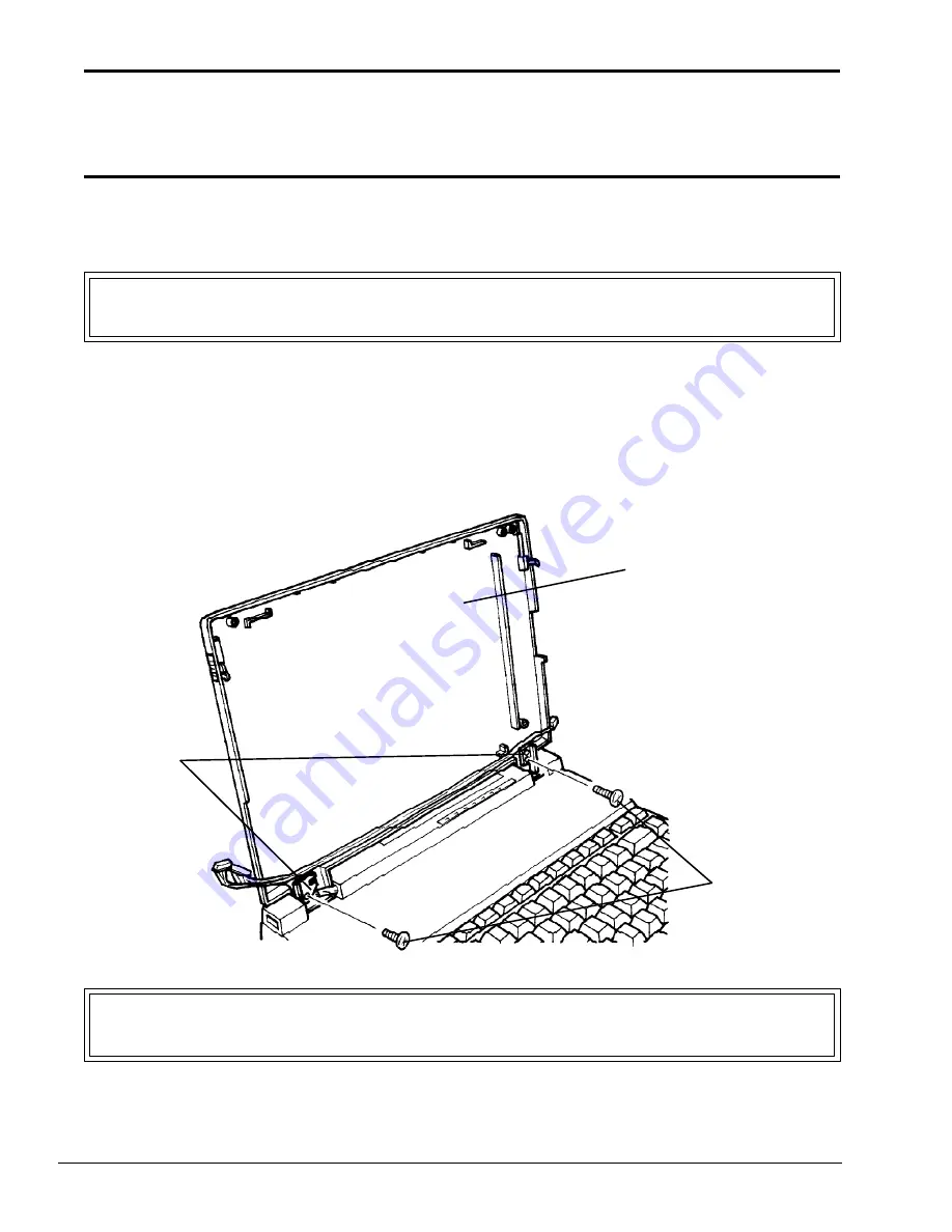
Rotate the two hinges toward the LCD cover and align the screw holes.
4.
Install the two (M2.5x4) screws into the lower screw holes to secure the LCD cover to the
hinges (Figure 6-15).
Figure 6-15 Installing the LCD cover
CAUTION: The LCD module must only be handled by its edges. NEVER touch the edge
containing the CAUTION label or you may permanently damage the module.
5.
Place the LCD module in the LCD cover. Align the lower left corner of the LCD module
M2.5x4 screws
LCD cover
hinges
Summary of Contents for T-Series T2200sx
Page 1: ...1 1 Chapter 1 Hardware Overview ...
Page 2: ...1 2 This page intentionally left blank ...
Page 4: ...1 4 This page intentionally left blank ...
Page 16: ...1 16 This page intentionally left blank ...
Page 17: ...2 1 Chapter 2 Operational Overview ...
Page 18: ...2 2 This page intentionally left blank ...
Page 43: ...3 1 Chapter 3 Troubleshooting Procedures ...
Page 44: ...3 2 This page intentionally left blank ...
Page 46: ...3 4 This page intentionally left blank ...
Page 82: ...3 40 This page intentionally left blank ...
Page 83: ...4 1 Chapter 4 Tests and Diagnostics ...
Page 84: ...4 2 This page intentionally left blank ...
Page 141: ...5 1 Chapter 5 Disassembly Procedures ...
Page 142: ...5 2 This page intentionally left blank ...
Page 144: ...5 4 This page intentionally left blank ...
Page 169: ...6 1 Chapter 6 Reassembly Procedures ...
Page 170: ...6 2 This page intentionally left blank ...
Page 172: ...6 4 This page intentionally left blank ...
Page 191: ...App 1 Appendices ...
Page 192: ...App 2 This page intentionally left blank ...
Page 196: ...App 6 Figure A 2 System board FSTFGx ICs back G G G G E F J H I K ...
Page 198: ...App 8 This page intentionally left blank ...
Page 200: ...App 10 Figure A 4 System board FSTFGx connectors back E A P Q ...
Page 202: ...App 12 This page intentionally left blank ...
Page 203: ...App 13 A 3 System Board FSTFGx OSCs Figure A 5 System board FSTFGx OSCs front F G H E ...
Page 204: ...App 14 Figure A 6 System board FSTFGx OSCs back A B C D ...
Page 215: ...App 25 Appendix C ASCII Character Codes Table C 1 ASCII character codes ...


