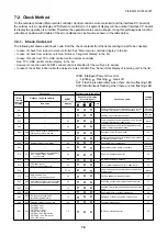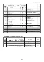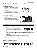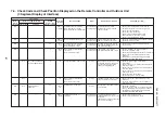
8
2
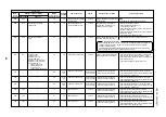
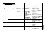
Check code
Main
remote
controller
E12
E15
E16
E18
E19
E20
E23
Outdoor 7-segment display
Check code
Sub-code
E12
01: Indoor/outdoor
communication
02: Between outdoors
communication
E15
—
E16
00: Capacity over
01 to: No. of connected units
—
—
E19
00: No header unit
02: Two or more header units
E20
01: Connection of outdoor of
other line
02: Connection of indoor of
other line
E23
—
AI-NET
central control
remote controller
42
42
89
97, 99
96
42
15
Detected
position
I/F
I/F
I/F
Indoor
unit
I/F
I/F
I/F
Check code name
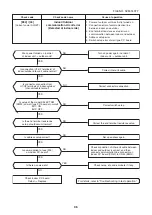
Automatic address start error
No corresponding indoor unit
during automatic address
No. of connected indoor units /
Capacity over
Communication error between
indoor header and follower
units
Outdoor header unit quantity
error
Other line unit connected
during automatic address
Communication sending error
between outdoor units
Status
All stop
All stop
All stop
Corresponding
unit only stops.
All stop
All stop
All stop
Error detection condition
• When indoor automatic address
started, other refrigerant circuit system
was setting automatic address.
• When outdoor automatic address
started, indoor automatic address was
executed.
Indoor unit is not found when indoor
automatic address start was set up.
• Total capacity of indoor units exceeded
135% of total outdoor capacity.
• No. of connected indoor units are more
than 48 units.
[Note]
If this code appears after backup setup
of outdoor unit trouble, set up “No
capacity-over detection”.
<Setup method of
“No capacity-over detection”>
Turn on SW09/Bit 2 on I/F P.C. board of
outdoor header unit.
Regular communication between indoor
header and follower units .
• There are multiple outdoor header
units in 1 line.
• There is none of outdoor header unit in
1 line.
Unit of other line was connected when
indoor automatic address started.
Transmission of other outdoor unit was
unavailable for 30 seconds or more.
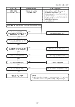
Check item (position)
• Setup the address again after disconnecting
communication connection with other refrigerant
circuit system.
• Check the communication line connection
between indoor and outdoor.
• Check the electric power line error in indoor.
• Check the noise of surrounding devices.
• Power failure
• Check indoor P.C. board error.
• Check the connection capacity of indoor unit.
• Check the HP capacity of indoor unit.
• Check the indoor/outdoor capacity setup
• Check the No. of connected indoor units.
• Check the outdoor I/F P.C. board error
• Check wire of the remote controller.
• Check power wiring of indoor.
• Check P.C. board of indoor.
• Check SW02 setup on the wall type P.C. board.
(Should be Bit 1: ON, Bit 2: OFF)
The outdoor unit connected with communication
wire between indoor and outdoor (U1.U2) is the
outdoor header unit.
• Check connection of communication line
between indoor and outdoor.
• Check outdoor P.C. board(I/F) error.
Separate the wire between lines according to
automatic address setup method in “Address
setup”.
• Check the power of outdoor unit.
(Is the power turned on?)
• Check connection of communication wire or
disconnection between outdoor units.
• Check the connector for communication on
outdoor P.C. board.
• Check outdoor P.C. board (I/F) error.
• Check the end terminal resistance setup for
communication between outdoor units.
FILE NO. SVM-1
40
77


