background image

1

6

3

CODE No. table (Please record the objective unit data at field)

Indoor unit capacity (CODE No. [11])

Initial value of EEPROM installed on the supplied service P.C. board

DN

01

02

03

06

0C

0d

0F

10

11

12

13

14

1E

28

2A

2b

2E

32

60

69

Item

Filter sign lighting time

Dirty state of filter

Central control address

Heating suction temp shift

PRE-DEF indication selection

Cooling auto mode existence

Cooling only

Type

Indoor unit capacity (See below table)

Refrigerant line address

Indoor unit address

Group address

Temp difference of automatic cooling/
heating selecting control points

Automatic restart from power cut

Option input selection (CN80)

Thermo output selection (T10 

S

)

Input selection (T10 

Q

)

Sensor selection

Timer set (Wired remote controller)

Louver selection of cooling

Memo

Be sure to set as 0008

At shipment

0001: 150 hour

0000: Standard

0099: Unfixed

0002: +2°C

0000: Standard

0001: No auto mode

Automatic selection by

cooling/heating

connected outdoor unit

0000: Heat pump

0008: High wall type

According to capacity type

0099: Unfixed

0099: Unfixed

0099: Unfixed

0003: 3deg (Ts ± 1.5)

0000: None

0002: External emergency input

0000: Thermo ON

0000: Operation input

0000: Available

0000: Available

0000: Standard

0001

0001

0003

0005

0007

0009

0011

Setup data


Model

Invalid

MMK-AP0073H

P-E1 (TR1)

MMK-AP0093H

P-E1 (TR1)

MMK-AP0123H

P-E1 (TR1)

MMK-AP0153H

P-E1 (TR1)

MMK-AP0183H

P-E1 (TR1)

MMK-AP0243H

P-E1 (TR1)

FILE NO. SVM-1

40

77

Summary of Contents for SUPER MMK-AP0073HP-E1 (TR1)

Page 1: ...P E1 TR1 MMK AP0123HP E1 TR1 MMK AP0153HP E1 TR1 MMK AP0183HP E1 TR1 MMK AP0243HP E1 TR1 This Service Manual describes contents of the new High Wall indoor unit For the outdoor unit refer to the Manual with FILE NO A03 009 A05 004 A05 015 The service parts will be supplied byTCTC ...

Page 2: ...PARTS RATING 10 4 REFRIGERATING CYCLE DIAGRAM 60 5 CONTROL OUTLINE 61 6 APPLIED CONTROL 68 7 TROUBLESHOOTING 75 8 CONFIGURATION OF CONTROL CIRCUIT 149 9 HOW TO REPLACE MAIN PARTS 151 10 REPLACEMENT OF SERVICE INDOOR P C BOARD 159 11 EXPLODED VIEWS AND PARTS LIST 164 2 FILE NO SVM 14077 ...

Page 3: ... is changed from one of the former R22 For an air conditioner which uses R410A never use other refrigerant than R410A For an air conditioner which uses other refrigerant R22 etc never use R410A If different types of refrigerant are mixed abnormal high pressure generates in the refrigerating cycle and an injury due to breakage may be caused Do not charge refrigerant additionally If charging refrige...

Page 4: ... heater stove or cocking stove though the refrigerant gas itself is innocuous When installing equipment which includes a large amount of charged refrigerant such as a multi air conditioner in a sub room it is necessary that the density does not the limit even if the refrigerant leaks If the refrigerant leaks and exceeds the limit density an accident of shortage of oxygen is caused For the installa...

Page 5: ... not mix in because pipes are affected by impurities such as water oxide scales oil etc Use the clean pipes Be sure to brazing with flowing nitrogen gas Never use gas other than nitrogen gas 4 For the earth protection use a vacuum pump for air purge 5 R410A refrigerant is azeotropic mixture type refrigerant Therefore use liquid type to charge the refrigerant If using gas for charging composition o...

Page 6: ...p meter 2 Thermometer 3 Insulation resistance tester 4 Electroscope Note 1 When flaring is carried out for R410A using the conventional flare tools adjustment of projection margin is necessary For this adjustment a copper pipe gauge etc are necessary Note 2 Charging cylinder for R410A is being currently developed General tools Conventional tools can be used In addition to the above exclusive tools...

Page 7: ...auge manifold Brazed Service port Service port Ø6 4 Copper pipe Ø6 4 Copper pipe Fully tightened Reducing valve Nitrogen gas Valve fully closed liquid side Connected to other terminal units Charge the refrigerant as below Recover the refrigerant and check there is no refrigerant in the equipment Leave it as it is for 1 to 2 minutes and check the indicator of the compound gauge does not return Set ...

Page 8: ...163 132 786 235 47 215 5 262 5 262 5 153 5 109 235 215 215 85 23 132 320 40 40 50 73 5 7 50 73 5 7 Front panel Air filter Heat exchanger Installation plate hanger Installation plate hanger Connecting pipe 0 39m 07 09 12 series 9 5mm 15 18 series 12 7mm 24 series 15 9mm Drain hose 0 5mm Connecting pipe 0 44m 07 09 12 series 6 4mm 15 18 series 6 4mm 24 series 9 5mm Air inlet Knock out system Knock o...

Page 9: ... CN309 YEL GRN YEL Color identification BRW BROWN RED RED WHI WHITE YEL YELLOW BLU BLUE BLK BLACK GRY GRAY PNK PINK ORN ORANGE GRN YEL GREEN YELLOW GRN GREEN Infrared rays receive and Indication parts MCC 5044 PNL EMG Option HA Fan drive Heat exchanger sensor TC1 BLK BLK TF WHI BLK 1 1 2 BLK BLK 1 1 2 1 2 2 3 3 2 6 5 4 3 2 5 4 3 2 1 10 10 Fan motor Power supply circuit Control P C board for indoor...

Page 10: ...cked from here Air filter Removes dirt or dust Provided in the air inlet grille No 1 2 3 4 5 6 Parts Name Fan motor for indoor Grille motor Thermo Sensor TA sensor Heat exchanger sensor TC1 sensor Heat exchanger sensor TC2 sensor Heat exchanger sensor TCJ sensor Type ICF 340 30 4 MF 340 30 1RT MP24Z3T 318mm Ø4 600mm Ø6 800mm Ø6 800mm Specications Output Rated 30W 280 340V DC Output Rated 1W 16 pol...

Page 11: ...Time of the timer with H mark is displayed When a trouble occurs the check code is displayed 5 Timer SET IN setup display When pushing the Timer SET IN button the display of the timer is selected in order of OFF OFF repeat OFF timer ON No display 6 Filter display If FILTER is displayed clean the air filter 7 TEST run display Displayed during a test run 8 Louver position display 4 way Air Discharge...

Page 12: ...ked unit in the group including 1 indoor unit by 1 outdoor unit 19 Unit Number display Unit number of the indoor unit selected with the unit select button or abnormal indication of the indoor outdoor unit 20 Central control display Displayed when the air conditioner is used under the central control in combination with a central control remote controller In case the remote controller is disabled b...

Page 13: ... when stopped Also it flashes when operating the protection device or abnormal time 9 ON OFF button When the button is pushed the operation starts and it stops by pushing the button again When the operation has stopped the operation lamp and all the displays disappear 10 MODE button Operation mode select button Selects desired operation mode 11 UNIT LOUVER button Unit Louver select button Selects ...

Page 14: ...tch at least 12 hours before starting operation Start 1 Push ON OFF button The operation lamp goes on and the operation starts 2 Select an operation mode with the MODE MODE button One push of the button and the display changes in the order shown as follows DRY mode function is not provided to Concealed Duct High Static Pressure Type 3 Select air volume with FAN button One push of the button and th...

Page 15: ...peration depending on the indoor temperature 3 5 Adjustment of Wind Direction For best cooling and heating performance adjust the louvers adjustment of up down wind direction appropriately CAUTION If cooling operation is performed with downward air outlet dew may fall on surface of the cabinet or the horizontal louver resulted in dripping If heating operation is performed with horizontal air outle...

Page 16: ...u make a swing or air direction setting at this time the remote controller display varies with the setting but the louvers stay pointed straight out horizontally When the air conditioner starts heating the louvers direct to the set direction As the refrigerant recovery control for the outdoor units in the Modular Multi system works even if the outdoor units stop in some cases the louver of the sto...

Page 17: ... SWING FIX set the louver adjustment plate of up down wind direction direction to the lowest position and then push SWING FIX again SWING is displayed and the up down wind direction is automatically selected Display during swinging In this case push SWING FIX again two seconds later In COOL DRY operation the louver does not stop as it directs downward If stopping the louver as it directs downward ...

Page 18: ... 23 5 hours 1 or number of days and time 24 hours or more 2 as shown below For every push of button the set time decreases in the unit of 0 5 hr 30 minutes 0 5 to 23 5 hours or 1 hr 24 to 168 hours Example of remote controller display In the case of 23 5 hours 1 In the case of 34 hours 2 shows 1 day 24 hours shows 10 hours Total 34 hours 3 Push SET button SETTING display disappears and timer time ...

Page 19: ...re a great deal of machine oil is used Do not install the air conditioner in a place where it is usually exposed to strong wind such as in seaside area Do not install the air conditioner in a place where sulfureous gas generated such as in a spa Do not install the air conditioner in a vessel or mobile crane Do not install the air conditioner in an acidic or alkaline atmosphere in a hot spring area...

Page 20: ...ndoor unit if it is very dirty Never use a damp cloth on the remote controller Do not use a chemically treated duster for wiping or leave such materials on the unit for long It may damage or fade the surface of the unit Do not use benzine thinner polishing powder or similar solvents for cleaning These may cause the plastic surface to crack or deform Periodic check Long period use of the air condit...

Page 21: ...t clogging scratches Sound Dust dirt breakage Vibration balance Dust dirt appearance Dust dirt scratches Dust dirt clogging drain contamination Dust dirt scratches Maintenance Wash the heat exchanger when it is clogged Take appropriate measures when abnormal sound is generated Wash the filter with water when it is contaminated Replace it when it is damaged Replace the fan when vibration or balance...

Page 22: ...h hard objects will cause scratches on the surface of the grille and the metal coating to peel off If very dirty clean the air inlet grille with a neutral detergent for kitchen use and rinse it off with water 3 Wipe out water from the air inlet grille and dry it 4 Fit the left and right arms of the air inlet grille to the shafts on the two sides of the air conditioner and push in completely and th...

Page 23: ...ind blows continuously against the air outlet of the outdoor unit Heating operation When dust or dirt is excessively adhered to air filter of the indoor unit When the air outlet of the indoor unit is blocked Cooling heating operation of Modular Multi system air conditioner In Modular Multi system air conditioner each indoor unit can be individually controlled However cooling operation and heating ...

Page 24: ...raining sound of dehumidifier This is sound generated when heat exchanger etc expand and contract slightly due to change of temperature Various smell such as one of wall carpet clothes cigarette or cosmetics adhere to the air conditioner When cooling operation cannot be performed because another indoor unit performs heating operation When the manager of the air conditioner has fixed the operation ...

Page 25: ...er 3 More details of the service code are explained in Service Manual Check these items If any of these problems still remains stop the operation turn off the leakage breaker and then notifies the dealer of the serial number and details of the error Never repair any part by yourself as it is dangerous When and a combination of or and a number are displayed on the remote controller also inform the ...

Page 26: ...or alternatively he or she has been instructed in such matters by an individual or individuals who have been trained and is thus thoroughly acquainted with the knowledge related to this work The qualified installer who is allowed to work at heights has been trained in matters relating to working at heights with the air conditioners made by Toshiba Carrier Corporation or alternatively he or she has...

Page 27: ...rotective gear is dangerous because you will be more susceptible to injury burns electric shocks and other injuries Work undertaken Protective gear worn All types of work Protective gloves Safety working clothing Electrical related work Gloves to provide protection for electricians and from heat Insulating shoes Clothing to provide protection from electric shock Work done at heights 50 cm or more ...

Page 28: ...RNING Moving parts Do not operate unit with grille removed Stop the unit before the servicing CAUTION High temperature parts You might get burned when removing this panel CAUTION High temperature parts You might get burned when removing this panel CAUTION Do not touch the aluminum fins of the unit Doing so may result in injury CAUTION Do not touch the aluminium fins of the unit Doing so may result...

Page 29: ...ing and removal Do not touch the aluminium fin of the unit You may injure yourself if you do so If the fin must be touched for some reason first put on protective gloves and safety work clothing and then proceed Do not climb onto or place objects on top of the outdoor unit You may fall or the objects may fall off of the outdoor unit and result in injury When work is performed at heights use a ladd...

Page 30: ... clothing to provide protection from electric shocks Failure to wear this protective gear may result in electric shocks Use wiring that meets the specifications in the Installation Manual and the stipulations in the local regulations and laws Use of wiring which does not meet the specifications may give rise to electric shocks electrical leakage smoking and or a fire Connect earth wire grounding w...

Page 31: ...jury or other trouble CAUTION New refrigerant air conditioner installation This air conditioner adopts the new HFC refrigerant R410A which does not destroy ozone layer The characteristics of R410A refrigerant are easy to absorb water oxidizing membrane or oil and its pressure is approx 1 6 times higher than that of refrigerant R22 Accompanied with the new refrigerant refrigerating oil has also bee...

Page 32: ...on Manual please refer to the enclosed CD R Owner s Manual 1 Hand over to customers For other languages that do not appear in this installation Manual please refer to the enclosed CD R CD ROM 1 Owner s Manual and Installation Manual Installation plate 1 Wireless remote controller 1 Battery 2 Remote controller holder 1 Mounting screw Ø4 25 6 Pan head wood screw Ø3 1 16 2 Screw Ø4 10 2 Heat insulato...

Page 33: ...tions where vapors from food oils are formed such as kitchens where food oils are used Blocked filters may cause the air conditioner s performance to deteriorate condensation to form the plastic parts to be damaged and other such problems to result Locations near obstructions such as ventilation openings or lighting fixtures where the flow of the blown air will be disrupted a disruption of the air...

Page 34: ...receiver should be avoided The microprocessor in the indoor unit should not be too close to RF noise sources For details see the owner s manual A C L For the rear left and left piping Wall Insert the cushion between the indoor unit and wall and tilt the indoor unit for better operation Do not allow the drain hose to get slack Cut the piping hole sloped slightly Make sure to run the drain hose slop...

Page 35: ...the following rules to prevent damage of the indoor units and human injury Do not put a heavy article on the indoor unit Even units are packaged Carry in the indoor unit as it is packaged if possible If carrying in the indoor unit unpacked by necessity be sure to use buffering cloth etc to not damage the unit To move the indoor unit do not apply force to the refrigerant pipe drain pan foamed parts...

Page 36: ...ling the installation plate with a mounting screw do not use the anchor bolt hole Otherwise the unit may fall down and result in personal injury and property damage CAUTION Failure to firmly install the unit may result in personal injury and property damage if the unit falls In case of block brick concrete or similar type walls make 5mm dia holes in the wall Insert clip anchors for appropriate mou...

Page 37: ...f the front panel for the bottom left or right connection with a pair of nippers 3 Changing drain hose For leftward connection bottom leftward connection and rear leftward connection s piping it is necessary to change the drain hose and drain cap Without changing the drain hose position the indoor unit will not fit to the wall How to remove the drain hose The drain hose can be removed by removing ...

Page 38: ... knife or a marking off pin cut them with a pair of nippers or an equivalent tool How to remove the drain hose 1 Remove the front panel 2 Remove the screws of drain hose 3 Pull out the drain hose How to fix the drain hose 1 Put the drain hose 2 Screw the drain hose to the indoor unit 3 Install the front panel 4mm No gap Do not apply lubricating oil refrigerant machine oil when inserting the drain ...

Page 39: ...m CAUTION Bind the auxiliary pipes two and power supply wiring and control wiring with facing tape tightly In case of leftward piping and rear leftward piping bind the auxiliary pipes two only with facing tape Carefully arrange pipes so that any pipe does not stick out of the rear plate of the indoor unit Carefully connect the auxiliary pipes and connecting pipes to one another and cut off the ins...

Page 40: ...crewed to the installation plate 8 DRAINAGE 1 Run the drain hose sloped downwards NOTE Hole should be made at a slight downward slant on the outdoor side 2 Put water in the drain pan and make sure that the water is drained out of doors 3 When connecting extension drain hose insulate the connecting part of extension drain hose with shield pipe CAUTION Arrange the drain pipe for proper drainage from...

Page 41: ... unit For details refer to the Installation Manual attached to the outdoor unit Flaring Cut the pipe with a pipe cutter Remove burrs completely Remaining burrs may cause gas leakage Insert a flare nut into the pipe and flare the pipe As the flaring sizes of R410A differ from those of refrigerant R22 the flare tools newly manufactured for R410A are recommended However the conventional tools can be ...

Page 42: ...on for the pipes should be done separately for the liquid side and gas side Because both of the liquid and gas side pipes become a low temperature during cooling operation sufficient heat insulation should be done to prevent condensation Heat insulator with a heat resistance of 120 C or more must be used for the gas side pipe The pipe connection section of the indoor unit must be heat insulated se...

Page 43: ... shock may be caused Be sure to use the cord clamps attached to the product Do not damage or scratch the conductive core and inner insulator of power and inter connecting wires when peeling them Use the power cord and Inter connecting wire of specified thickness type and protective devices required Never connect 220 240V power to the terminal blocks etc for control wiring Otherwise the system will...

Page 44: ... line Wired remote controller wiring This wiring is not required when using the supplied wireless remote controller For wiring remote controllers a 2 core non polarity wire must be used CAUTION The remote controller wire Communication line and AC220 240V wires cannot be parallel to contact each other and cannot be stored in the same conduits If doing so a trouble may be caused on the control syste...

Page 45: ...U2 U1 U2 U3 U4 L1 L2 L3 N U5 U6 L N A B A B 380V 415V 50Hz 380V 60Hz U1 U2 U3 U4 L1 L2 L3 N U5 U6 U1 U2 L N A B A B U1 U2 L N A B A B U1 U2 L N A B Outdoor Power supply Earth terminal Earth terminal Outdoor Power supply Earth leakage breaker Earth leakage breaker Header outdoor unit Follower outdoor unit Control wiring between outdoor units Control wiring between indoor and outdoor units Control w...

Page 46: ...s no problem if connections to indoor unit terminal blocks A and B are reversed Wiring diagram A B A B Terminal block for remote controller wiring of indoor unit Wired remote controller wire Procured locally Terminal block Wired remote controller unit 1111050501_01EN_SMMS_HighWall_IM_B5 book Page 18 Wednesday November 12 2008 2 45 PM ...

Page 47: ...rew 9 Clamp the power supply wire with the cord clamp 10 Attach the terminal cover and the air inlet grille to the indoor unit CAUTION Be sure to refer to the wiring diagram attached inside the front panel Check local electrical cords and also any specific wiring instructions and limitations Do not catch the control wire when installing the clamp base A B U1 U2 A B Terminal block for control wired...

Page 48: ... selector unit with the cord clamp 8 Install the clamp base with a screw 9 Insert the power supply wire fully into the terminal block and secure it tightly with screws Tightening torque 1 2 N m 0 12 kgf m Secure the earth line with the earth screw 10 Clamp the power supply wire with the cord clamp 11 Insert the power supply wire fasten terminal of the flow selector unit into the power supply termi...

Page 49: ...tent for setting differs from that on the former types of remote controller RBC AMT21E AMT31E The number of CODE No has increased Procedure 1 Push button and TEMP button simultaneously for at least 4 seconds After a while the display flashes as shown in the figure Confirm that the CODE No is 10 If the CODE No is not 10 push button to erase the display content and repeat the procedure from the begi...

Page 50: ...peration of the remote controller is accepted Change of lighting time of filter sign According to the installation condition the lighting time of the filter sign Notification of filter cleaning can be changed Follow to the basic operation procedure 1 2 3 4 5 6 For the CODE No in Procedure 3 specify 01 For the SET DATA in Procedure 4 select the SET DATA of filter sign lighting time from the followi...

Page 51: ...a group control The wireless remote controller is unavailable for this control For cabling procedure and cables of the individual line Identical refrigerant line system refer to Electric work in this Manual Cabling between indoor units in a group is performed in the following procedure Connect the indoor units by connecting the remote controller inter unit cables from the remote controller termina...

Page 52: ...the operation refer to the attached Owner s Manual A forced test run can be executed in the following procedure even if the operation stops by thermo OFF In order to prevent a serial operation the forced test run is released after 60 minutes have passed and returns to the usual operation CAUTION Do not use the forced test run for cases other than the test run because it applies an excessive load t...

Page 53: ...oor units 1 When pushing button for 10 seconds or more Pi sound is heard and the operation changes to a forced cooling operation After approx 3 minutes a cooling operation starts forcedly Check cool air starts blowing If the operation does not start check wiring again 2 To stop a test operation push button once again Approx 1 second The louver closes and the operation stops Check transmission of r...

Page 54: ... history is stored in memory up to 4 troubles The history can be confirmed from both operating status and stop status Procedure 1 When pushing and buttons at the same time for 4 seconds or more the following display appears If Service check is displayed the mode enters in the trouble history mode 01 Order of trouble history is displayed in CODE No window Check code is displayed in CHECK window Ind...

Page 55: ...ent display Sensor block display of receiving unit Auxiliary code OPERATION TIMER PRE DEF Flash E01 Communication error between indoor and remote controller Detected at remote controller side Remote controller E02 Remote controller transmission error Remote controller E03 Communication error between indoor and remote controller Detected at indoor side Indoor E04 Communication circuit error between...

Page 56: ...or I F H01 H01 01 Comp 1 side 02 Comp 2 side Compressor break down IPDU H02 H02 01 Comp 1 side 02 Comp 2 side Magnet switch error Overcurrent relay operation Compressor trouble lock MG SW Overcurrent relay IPDU H03 H03 01 Comp 1 side 02 Comp 2 side Current detect circuit system error IPDU H04 H04 Comp 1 case thermo operation I F H06 H06 Low pressure protective operation I F H07 H07 Oil level down ...

Page 57: ... P17 P17 ALT Discharge temp TD2 error I F P19 P19 Detected outdoor unit number ALT 4 way valve inverse error I F P20 P20 ALT High pressure protective operation I F P22 P22 0 IGBT short 1 Fan motor position detective circuit error 3 Fan motor trouble C TH sensor temp error Heat sink overheat D TH sensor error E Vdc output error ALT Outdoor fan IPDU error IPDU P26 P26 01 Comp 1 side 02 Comp 2 side A...

Page 58: ...1 If there are 2 or more refrigerating systems in a single refrigerating device the amounts of refrigerant should be as charged in each independent device For the amount of charge in this example The possible amount of leaked refrigerant gas in rooms A B and C is 10kg The possible amount of leaked refrigerant gas in rooms D E and F is 15kg NOTE 2 The standards for minimum room volume are as follow...

Page 59: ...EILING 1 0001 HIGH CEILING 3 0003 Have you changed lighting time of filter sign If not fill check mark in NO CHANGE and fill check mark in ITEM if changed respectively For check method refer to Applicable controls in this sheet Filter sign lighting time CODE No 01 NO CHANGE NONE 0000 150H 0001 2500H 0002 5000H 0003 10000H 0004 Filter sign lighting time CODE No 01 NO CHANGE NONE 0000 150H 0001 2500...

Page 60: ...ector CN100 3P Brown 1 Controls PMV super heat in cooling operation Connector CN101 2P Blue 1 Controls PMV under cool in heating operation Connector CN102 2P Yellow 1 Controls PMV super heat in cooling operation FILE NO SVM 14077 Liquid side Gas side Strainer Capillary tube Air heat exchanger at indoor side Strainer Fan M Fan motor Sensor TCJ Sensor TC2 Sensor TC1 Sensor TA ...

Page 61: ...ation Dry operation Heating operation Ta and Ts automatically select COOL HEAT operation mode for operation Except SHRM the automatic mode cannot be selected While a wireless remote controller is used the mode is notified by Pi Pi two times receiving sound To clear the alternate flashing change the mode on the wireless remote controller 1 Adjustment range Remote controller setup temperature C Wire...

Page 62: ... below based upon temp detected by TC2 and TCJ sensors When M zone is detected for 45 minutes the thermostat is forcedly off In N zone the timer count is interrupted and held When shifting to M zone again the timer count restarts and continues If L zone is detected the timer is cleared and the operation returns to normal operation Reset conditions 1 TC1 12 C and TC2 12 C and TCJ 12 C 2 20 minutes ...

Page 63: ... to COOL HEAT selection ready for operation and protectiv e control 1 When the unit stopped from HEAT operation the indoor fan operates with L for approx 30 seconds 1 ON OFF operation is av ailable by input of HA signal from the remote site when connected to remote controller or the remote ON OFF interface 2 HA control outputs ON OFF status to HA terminal 3 The I O specifications of HA conform to ...

Page 64: ...tents that can be operated by the remote controller at the indoor unit side is possible according to setting at the central controller side 2 Setting contents In case of TCC LINK central control Operation from TCC LINK central control Individual Central 1 Central 2 Central 3 Central 4 Operation on RBC AMT32E ON OFF Operation Timer Temp Air speed Air direction setting selection setting setting sett...

Page 65: ...ent during cooling dry and heating operation 4 When the unit stopped or the warning was output the louver is automatically set to full closed position 5 When PRE HEAT is displayed Heating operation started or defrost operation is performed heating thermo is off the louver is automatically set to horizontal discharge position When you push the Hi POWER button during cooling heating or A operation t...

Page 66: ...pacity is kept to the minimum overheating is prevented by lowering the temperature setting by 1 C after 1 hour and by 2 C after 2 hours of operation The room temperature is thus regulated between the set temperature and the operation suppression zone When the OFF timer is simultaneously set 1 3 5 and 9 hours appear by turns every pushing COMFORT SLEEP button and one of them can be selected for OFF...

Page 67: ...y will indicate AUTO and low speed will be used Remarks display When the OFF timer is set 1 3 5 and 9 hours appear by turns every pushing SLEEP button and one of them can be selected for OFF timer SLEEP operation Wireless remote controller specific operation 21 22 Save operation 1 The function Save operation is not provided to the Super Modular Multi series models If pushing SAVE button on the rem...

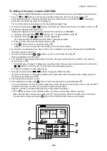
Page 68: ...of the selected indoor unit is turned on 2 Every pushing UNIT LOUVER button the indoor unit numbers in the group control are successively displayed In this time the fan of the selected indoor unit only is turned on 3 Specify the item code DN using the setup temperature and buttons 4 Select the setup data using the timer time and buttons When selecting the DN code to 33 change the temperature indic...

Page 69: ... 0002 2 C to 0003 3 C 0010 10 C Up to 6 recommended 0000 Provided 0001 Not provided Automatic selection from connected outdoor unit 0000 Heat pump 0001 Cooling only No display of AUTO HEAT 0008 High Wall 0000 Unfixed 0001 to 0034 0001 No 1 unit to 0030 No 30 unit 0001 No 1 unit to 0064 No 64 unit 0000 Individual 0001 Header unit of group 0002 Follower unit of group 0000 0 deg to 0010 10 deg For se...

Page 70: ...gnal Output during alarm Serial communication error or indoor outdoor protective device operation 2 Wiring diagram using remote control interface TCB IFCB 4E2 Input IFCB 4E2 No voltage ON OFF serial signal Output No voltage contact for operation error display Contact capacity Below Max AC240V 0 5A Setup data 0008 Type High Wall Abbreviated Model name MMK AP XXX HP Setup data 0001 0003 0005 0007 00...

Page 71: ... set up the wired remote controller to the header unit Same in group control In a group control if the wired remote controller is set up to the header unit both header and follower units are simultaneously operable 1 Push concurrently SET CL TEST buttons for 4 seconds or more The unit No displayed firstly indicates the header indoor unit address in the group control In this time the fan of the sel...

Page 72: ...or unit can be protected When inserting a card start stop operation from the remote controller is allowed When taking out a card the system stops if the indoor unit is operating and start stop operation from the remote controller is forbidden 1 Control items 1 Outside contact ON The start stop operation from the remote controller is allowed Status that card is inserted in the card switch box 2 Out...

Page 73: ...V Fan drive CN32 DC 12V Louver CN33 DC 20V DC fan input output CN210 Terminator resistor provided not provided Remote controller A B switch SW01 Display output Wireless sensor CN213 DC 5V Option power supply CN309 AC 200V Central control CN40 DC 5V TCJ sensor CN102 DC 5V Microcomputer operation LED D02 TC sensor CN101 DC 5V EEPROM IC10 Inter unit wire CN67 AC 200V n Indoor P C Board MCC 1510 FILE ...

Page 74: ...ration by FAN button on remote controller is executed from remote controller DN 31 HA Start Stop input J01 Provided Not provided Pulse At shipment from factory Static input switch Operation stop of handy remote controller is permitted prohibited by input ON during operation Answer back of HA ON during output of alarm ON during defrosting of outdoor unit ON when Real thermo ON Comp ON ON when opera...

Page 75: ...communicating Is not the cold draft prevention being controlled in heating operation Is not low cooling operation being controlled Is not a defrost operation being performed Is not after heat elimination operation being controlled after heating operation Is not auxiliary unit or remote control being operated Is connecting wire of indoor unit or remote controller correct 2 Troubleshooting procedure...

Page 76: ...on between outdoor units E15 E16 00 Capacity over 01 No of connected units E19 00 No header unit 02 Two or more header units E20 01 Outdoor of other line connected 02 Indoor of other line connected E23 E25 E26 No of outdoor units which received signal normally E28 Detected outdoor unit number 01 IPDU1 error 02 IPDU2 error 03 IPDU1 2 error E31 04 Fan IPDU error 05 IPDU Fan IPDU error 06 IPDU2 Fan I...

Page 77: ...door TCJ sensor error Indoor TC2 sensor error Indoor TC1 sensor error TD1 sensor error TD2 sensor error TE1 sensor error TL sensor error TO sensor error Indoor TA sensor error TS1 sensor error TH sensor error Outdoor temp sensor misconnecting TE TL Outdoor pressure sensor misconnecting Pd Ps Ps sensor error Pd sensor error Indoor other error Outdoor EEPROM error Compressor break down Magnet switch...

Page 78: ...overheat error Indoor fan motor error Outdoor liquid back detection error Gas leak detection Discharge temp TD2 error 4 way valve inverse error High pressure protective operation Outdoor fan IPDU error G TR short protection error Comp position detective circuit system error Other indoor unit error Group follower unit error Error in indoor group AI NET communication system error Duplicated network ...

Page 79: ...oner the error history can be confirmed with the following procedure Up to 4 error histories are stored in memory This history can be confirmed from either operating status or stop status Description When pushing SET and TEST buttons simultaneously for 4 seconds or more the below display appears If Service Check is displayed the mode enters in the error history mode 01 Error history order is displ...

Page 80: ...firmation of error history When a trouble occurred on the air conditioner the error history can be confirmed with the following proce dure Up to 4 error histories are stored in memory This history can be confirmed from either operating or stop 1 Push and SET buttons in succession for 4 seconds or more 2 SERVICE CHECK goes on and Item code 01 goes on 3 When selecting flash the group number if there...

Page 81: ...d from the indoor unit which has been used to send signals E06 is normally displayed Transmission from outdoor to indoor cannot continue for 30 seconds Multiple indoor unit address setup are duplicated In 2 remote controller control including wireless both are setup as master Header indoor unit stops and other indoor unit is operating Check item position Check remote controller inter unit wire A B...

Page 82: ...n SW09 Bit 2 on I F P C board of outdoor header unit Regular communication between indoor header and follower units There are multiple outdoor header units in 1 line There is none of outdoor header unit in 1 line Unit of other line was connected when indoor automatic address started Transmission of other outdoor unit was unavailable for 30 seconds or more Check item position Setup the address agai...

Page 83: ... or zero Open Short Resistance value of sensor is infinite or zero Open Short Check item position Note Do not set up the outdoor address manually Outdoor is performing backup Check the power of outdoor unit Is the power turned on Check connection of inter unit wire or disconnection between outdoor units Check the connector connection for communication on outdoor P C board Check outdoor P C board I...

Page 84: ...d not operate normally Outdoor P C board I F did not operate normally Inverter current detection circuit detected over current and stopped Check item position Check connection of TL sensor connector Check characteristics of TL sensor resistance value Check outdoor P C board I F error Check connection of TO sensor connector Check characteristics of TO sensor resistance value Check outdoor P C board...

Page 85: ... due to liquid stagnation in compressor Check outdoor P C board IPDU error Check outdoor MG SW or OCR Check wiring of current detection circuit system Check outdoor P C board IPDU error Check compressor 1 case thermo circuit Connector wire P C board Check full opening of service valve Gas and liquid side Check outdoor PMV clogging PMV1 2 Check SV41 circuit leakage Check miscabling misinstallation ...

Page 86: ...r Check connection of TK3 sensor connector Check characteristics of TK3 sensor resistance value Check outdoor P C board I F error Check connection of TK4 sensor connector Check characteristics of TK4 sensor resistance value Check outdoor P C board I F error Check compressor 2 case thermo circuit Connector wire P C board Check full opening of service valve Gas and liquid side Check outdoor PMV clog...

Page 87: ...ts in a group Line address setup is duplicated against the outdoor unit in different refrigerant pipe system Indoor units with priority were duplicated Indoor units with priority were duplicated At least one indoor unit connected to a group existed in the individual indoor units Address was not yet set up Indoor unit capacity was unset On the I F P C board for service jumper line was not cut accor...

Page 88: ...ide device error 2 Check indoor P C board error n Outside device is not connected to connector CN80 1 Check indoor P C board error Check indoor I F P C board Check the lock of fan motor AC fan Check wiring Check full opening of outdoor service valves Gas side Liquid side Check clogging of outdoor PMV PMV1 2 Check characteristics of TD1 sensor resistance value Check refrigerant shortage Check 4 way...

Page 89: ... voltage Check outdoor fan system error Check clogging of heat sink cooling duct Check fixation between IGBT and heat sink Check screwing and contact Check IPDU error IGBT built in temp sensor TH error Check connection of fan connector and wiring Check fan motor error Check indoor P C board error Check influence of outside air control Check indoor type code DN 10 and the capacity code DN 11 Check ...

Page 90: ...E Input power supply voltage of the fan IPDU over the setup value was detected Input power supply terminal of the fan IPDU was unconnected Power supply P C board error of the fan IPDU Check item position Check Pd pressure sensor error Check full opening of service valves Gas side Liquid side Check outdoor fan error Check outdoor fan motor error Check clogging of outdoor PMV PMV1 2 Check clogging o...

Page 91: ...lower unit error Status All stop All stop Corresponding unit only stops Error detection condition Instantaneous over current was detected when compressor started Position was not normally detected E07 L07 L03 L08 was detected when other indoor unit in the group was defective Check item position Check connector connection and wiring on IPDU P C board Check compressor error and defect of compressor ...

Page 92: ...rol device error Check communication line error of central control device Check setup of end terminal resistance Check central control device error Check communication line error of central control device Check setup of end terminal resistance Check the power of connecting destination connected device Check P C board error of the connected device Check error input Check the check code of the unit ...

Page 93: ...terminal lug If it is loosened caulk it with pinchers etc and then connect lead to the terminal 7 4 3 How to Check Resistance of Compressor Winding 1 Turn off the power supply 2 Remove the compressor lead cables from the compressors In each compressor check the winding resistance between phases and resistance of the outdoor cabinet using a tester Is not it earthed Normal if 10MΩ or more are measur...

Page 94: ...nter unit cable of remote controller Correct connector connection and check circuit cabling Check power connection status of indoor unit Turn on power again Check indoor P C board Defect Replace Change one to main other to sub Remote controller address connector Check remote controller P C board Defect Replace Check code E01 Current code AI NET Check code name Communication error between indoor an...

Page 95: ...ication adaptor This error is detected when the indoor unit cannot receive a signal from the remote controller Check communication cables of the remote controllers A and B As communication is impossible this check code E03 is not displayed on the main remote controller It is displayed on TCC LINK central controller It is not displayed on 7 segment display of the central control controller YES NO I...

Page 96: ...utdoor inter unit cable normal Was power turned on in order of indoor unit outdoor unit Is the end terminal resistance setup of outdoor unit normal Is power applied to fuse F03 on indoor P C board Is connection U1 U2 terminals of indoor outdoor inter unit cable normal YES Check indoor P C board Defect Replace Check connection of inter unit cable between indoor and outdoor is correct and then conne...

Page 97: ... is not sent for a certain period from the indoor unit which has used to send signals normally E06 is displayed Is power of indoor turned on Did a power failure occur Is there no noise etc YES YES YES YES YES YES NO NO NO NO NO NO Is there no miscabling disconnection on communication line betweenindoor and outdoor Is connection of CN40 connector on indoor P C board normal Is connection of CN01 con...

Page 98: ...inter unit cable U1 U2 between indoor and outdoor short circuited Is connection of inter unit cable between indoor and outdoor correct Is there no error on power cable to outdoor unit Is F400 fuse on I F P C board opened Outdoor I F P C board failure Replace Eliminate noise Correct power cable Correct communication line I F P C board failure However an emergent operation is available by inserting ...

Page 99: ...cted to the different outdoor unit Is indoor unit quantity connected to outdoor unit correct Set up indoor address again Correct communication line Correct cable connection NO Correct switch setup YES Is setup of the model SELECT SW SW02 on wall type P C board of normal Bit 1 ON Bit 2 OFF Check code E09 99 Current code AI NET Check code name Duplicated master remote controller Cause of operation S...

Page 100: ...m surrounding devices 4 Power failure 5 Indoor P C board error YES NO Are U1 U2 U3 and U4 connectors connected Disconnect connector connection of U1 U2 U3 and U4 Set up address again Refer to Address setup procedure Turn on power of outdoor unit again YES YES YES YES YES YES NO NO NO NO NO NO Did a power failure occur Is there no noise source Is connection of CN01 connector on I F P C board of hea...

Page 101: ...N Usually OFF YES YES YES YES NO NO NO NO OK NG Is backup operation of outdoor unit being set up Is No of connected indoor units correct Is setup of indoor unit HP correct Is total capacity of connected indoor units within 135 For a service P C board check outdoor HP setup Set up jumper 9 10 11 and 12 Set up outdoor HP Refer How to exchange interface P C board Set capacity of connected indoor unit...

Page 102: ...or address Correct indoor address Is there any disconnection of connector or wiring from terminal block of indoor unit Are remote controller inter unit cables A B normal Are powers of all indoor units turned on Check indoor P C board Failure Replace Check power connection status of indoor unit Correct connection of connector Check circuit wire Correct remote controller inter unit wire YES NO Corre...

Page 103: ... 1 system Check I F board Connect communication line between indoor and outdoor Connect communication line between indoor and outdoor to one unit per 1 system Check code E20 42 Current code AI NET Reference An outdoor unit connected with communication wires U1 U2 between indoor and outdoor is the header unit Check code name Unit connected to other line during automatic address Cause of operation W...

Page 104: ...O NO Did power failure occur Is there no noise source etc Is there no miscabling or disconnection on communication line between outdoor units Is the end terminal resistance between outdoor units turned on SW30 Bit 1 Is connection of CN03 connector on outdoor I F P C board normal Check outdoor I F P C board Defect Replace Is not main power of outdoor unit turned off Check and eliminate noise etc Cl...

Page 105: ...n 5 Outdoor I F P C board error Sub code No of outdoor units which received signals normally 1 How to clear the error Set SW01 SW02 SW03 on I F P C board of header unit to 2 16 1 and push SW04 for 5 seconds or more 7 segment display Er CL YES YES YES YES NO NO NO NO Is outdoor unit setting backup Is main power of follower unit turned on Is communication line between outdoor units connected normall...

Page 106: ...d I F P C board 2 I F P C board error 3 IPDU P C board error 4 External noise Sub code 01 IPDU1 error 02 IPDU2 error 03 IPDU1 2 error 04 Fan IPDU error 05 IPDU1 fan IPDU error 06 IPDU2 fan IPDU error 07 All IPDU error or communication line error between IPDU I F P C boards or outdoor I F P C board error If the fan IPDU is abnormal be sure to check the voltage output on the fan power supply P C boa...

Page 107: ...llow on indoor P C board normally connected Are characteristics of TCJ sensor resistance value normal Check indoor main P C board Defect Replace Indoor unit temperature sensor characteristics See Characteristics 2 Correct connection of connector Replace TC2 sensor Is TC2 sensor connector CN101 Blue on indoor P C board normally connected Are characteristics of TC2 sensor resistance value normal Che...

Page 108: ...r connection of connector TD2 sensor CN503 Pink and characteristics of sensor resistance value Refer to Outdoor unit temperature sensor characteristics If sensor is normal replace outdoor I F P C board Check code F06 18 Current code AI NET Check code name TE1 sensor error Cause of operation TE1 sensor Open Short This error code means detection of Open Short of TE1 sensor Check disconnection of cir...

Page 109: ...r unit temperature sensor characteristics If sensor is normal replace outdoor I F P C board Check code F10 0C Current code AI NET Check code name Indoor TA sensor error Cause of operation TA sensor Open Short This error code means detection of Open Short of TA sensor Check disconnection of circuit for connection of connector TA sensor CN104 White and characteristics of sensor resistance value Refe...

Page 110: ...cteristics error of TE1 sensor and TL sensor 3 Outdoor P C board I F error YES YES YES NO NO NO Are installed positions of TE1 sensor and TL sensor correct Are connection of TE1 sensor connector and TL sensor connector normal Are resistance characteristics of TL sensor and TE1 sensor normal Check outdoor I F P C board Defect Replace Correct connection of connectors Correct connection of connectors...

Page 111: ... connectors correct Are output voltage characteristics of Pd sensor and Ps sensor normal Are Pd Ps output values Pd Ps during compressor operation Check outdoor I F P C board Defect Replace Value can be confirmed by 7 segment display function on outdoor I F P C board Pd SW01 02 03 1 1 2 Ps SW01 02 03 1 2 2 1 Pressure Check joint by pressure gauge 2 Pressure display on 7 segment display 3 Output vo...

Page 112: ...auge 2 Pressure display on 7 segment display 3 Output voltage of I F P C board If 1 and 2 3 are different an error of pressure sensor itself is considered If 2 and 3 are different check interface P C board Connector CN500 White Correct connection of connector Check 4 way valve Check compressor Check code F24 43 Current code AI NET Check code name Pd sensor error Cause of operation Output voltage e...

Page 113: ...is repeated In this case 97 error is displayed on AI NET central controller Approx 3 minutes Approx 1 minute Power ON SET DATA is displayed on main remote controller SET DATA disappears LED D02 1Hz flashes for approx 10 seconds on indoor unit P C board Repeat Reset Repetition Check code F31 1C Current code AI NET Check code name Outdoor EEPROM error Cause of operation 1 Outdoor unit power error Vo...

Page 114: ... Does voltage drop occur when other compressor starts Is connection of wiring or connection of connector on IPDU P C board normal Correct power line Correct connector connection or wiring Correct cause of overload Compressor error Motor burning etc Note 1 After checking the output when connecting the compressor lead again to the compressor terminal check surely there is no distortion on the Fasten...

Page 115: ...connector connection on IPDU P C board normal Is there no refrigerant stagnation in compressor shell Correct power line Correct cause of overload Compressor error Correct connector connection or wiring Correct refrigerant stagnation in compressor shell 1 380 415V 10 2 Check the following items mainly 1 Existence of abnormal sound and abnormal vibration during operation or starting 2 Abnormal overh...

Page 116: ...or Cause of operation 1 Cabling or connector connection error on IPDU P C board 2 IPDU P C board error Sub code 01 Compressor 1 side 02 Compressor 2 side YES NO Check IPDU P C board Correct connector connection or cabling Wiring or connector connection on IPDU P C board normal FILE NO SVM 14077 ...

Page 117: ...Never touch with hands 3 Current of compressor lead during operation or starting No rapid current change SV4 valve Connector CN311 Blue Connector CN300 301 White Is compressor normal Note 2 Repair case thermo circuit Are service valves of gas pipe and liquid pipe of outdoor unit fully opened Does not refrigerant bypass from discharge of suction through 4 way valve Refrigerant shortage clogging pip...

Page 118: ... NO NO NO NO NO NO Open service valves fully Exchange low pressure sensor Correct SV2 and SV4 circuits Correct cabling Are SV2 and SV4 circuits normal Are service valves of gas and liquid pipe of outdoor unit fully opened Is not indoor unit with different circuit connected In cooling season go to A In heating season go to B Does indoor fan normally operate in cooling season Are characteristics of ...

Page 119: ... valves SV3A SV3C of all outdoor units in the same line 3 Check refrigerant stagnation in compressor Are characteristics of TK1 to TK4 of error detected unit normal Are balance pipe valves of all outdoor units in same line fully opened Open balance pipe valves fully reset power supply and start operation Are TK1 TK2 TK3 and TK4 sensors of the error detected unit correctly connected Is there no sen...

Page 120: ...s or more Set up SW02 9 and turn on SV3A SV3B SV3C valves 7 segment display Hr 3 While outdoor unit is operating check temperature change at secondary side of SV3B valve in the figure If temperature does not rise equivalent to suction temperature it is a clogging of SV3B valve Replace SV3B valve d Clogging for SV3E valve Reset the power supply ò Referring to Valve forced open close function of the...

Page 121: ...ered R in the figure 4 a Clogging check for oil equalization circuit Drive the outdoor unit Drive both compressors in the unit After driving for 10 minutes check temperature of TK1 and TK2 sensors and temperature of oil equalization circuit capillary W in the figure were raised Criterion TK1 TK2 Td1 Td2 temperature Approx 10 to 30 C Oil equalization capillary tubes should be higher sufficiently th...

Page 122: ...agnation in case of compressor shell Is not TK1 sensor detached Is there no miscabling or misinstallation on TK1 TK2 TK3 TK4 sensors Start a test operation in COOL or HEAT mode TK1 sensor temp is displayed on 7 segment display with SW01 02 03 1 11 2 Check TK1 sensor temp approx 10 minutes after compressor 1 has operated If low temperature continues approximately outside temp or temperature does no...

Page 123: ...ues approximately outside temp or temperature does not almost change a clogging of strainer of oil equalization circuit clogging of capillary or malfunction of check valve is considered 1 Refer to item H07 error 2 If OCR operates even after manual reset of OCR check whether the wiring to the current sensor TO2 of Comp IPDU is correct or not Outdoor unit temp sensor characteristics 4 Correct miscab...

Page 124: ... 1 13 2 Check TK3 sensor temp approx 10 minutes after compressor 2 has operated If low temperature continues approximately outside temp or temperature does not almost change a clogging of parallel capillary is considered Note 1 Refer to item H07 error Outdoor unit temp sensor characteristics 4 Correct miscabling misinstallation TK1 CN514 TK2 CN515 TK3 CN516 TK4 CN523 YES YES YES NO NO NO Check I F...

Page 125: ...re no miscabling or misinstallation on TK1 TK2 TK3 TK4 sensors Check the clogging of SV3E valve 1 Refer to item H07 error 2 If OCR operates even after manual reset of OCR check whether the wiring to the current sensor TO2 of Comp IPDU is correct or not Correct miscabling misinstallation TK1 CN514 TK2 CN515 TK3 CN516 TK4 CN523 YES YES YES NO NO NO Replace SV3E valve Correct installation of sensor A...

Page 126: ...ress Cause of operation Outdoor line addresses are duplicated YES YES NO NO Correct the line address setup Correct the cable connection Is there duplicated line address setup Are communication cable connections of U1 U2 U3 U4 and U5 U6 normal Check outdoor I F P C board Failure Replace Re set up the address Refer to Address setup Check code L05 96 Current code AI NET Check code name Duplicated ind...

Page 127: ...splayed on the unit other than the setup indoor unit and outdoor unit As only one indoor unit with priority is valid change the setup Check code L07 99 Current code AI NET Check code name Group line in individual indoor unit Cause of operation The group line is connected in the individual indoor unit Is there group cabling Check indoor P C board Failure Replace There is individual indoor unit Corr...

Page 128: ...n the power of outdoor unit again Are powers of all the indoor units turned on Disconnect connectors between U1 U2 and U3 U4 Clear addresses Refer to Address clear Re execute address setup Refer to Address setup YES NO Check code L09 46 Current code AI NET Check code name Indoor capacity unset Cause of operation Indoor capacity unset Set up capacity data of indoor unit Setup item code DN 11 Check ...

Page 129: ...entral control addresses are duplicated Are not two or more central control system identical network addresses connected Check the network adaptor on the indoor P C board Correct the network address of the central control system YES NO Check code L28 46 Current code AI NET Check code name Quantity over of connected outdoor units Cause of operation 1 Quantity over of connected outdoor units 2 Conne...

Page 130: ...rouble Correct connection of connector Replace communication line I F P C board error I F P C board error Correct connection of connector Is there voltage fluctuation between 4 and 5 pins of CN600 on I F P C board Measurement by tester DC0 to 5V 5 pin GND Is there voltage fluctuation between 3 and 5 pins of CN600 on I F P C board Measurement by tester DC0 to 5V 5 pin GND Is jumper setup of outdoor...

Page 131: ...ce connected to connector CN80 Check indoor P C board Failure Replace Check outside device Failure Replace YES YES NO NO Check code L31 Current code AI NET Check code name Extended IC error Cause of operation 1 Outdoor unit power error 2 Outdoor I F P C board error Check outdoor I F P C board Is there any trouble of outdoor unit power supply Check power voltage and line Check auxiliaty noise etc N...

Page 132: ...or replace SV41 valve Are characteristics of TD1 sensor resistance normal Are service valve of gas and liquid sides fully opened Are not indoor units of different refrigerant circuit connected Refrigerant shortage clogging pipe breakage Connector CN300 301 White Refer to Outdoor unit temperature sensor characteristics 4 Check there is no pipe breakage and then recharge the refrigerant Check with m...

Page 133: ... operate Are parts of high pressure SW normal Is service valve fully opened B Cooling operation Is SV2 circuit normal Open service valve fully Replace the high pressure sensor Repair faulty parts Eliminate the interfered causes Repair SV2 circuit Is circuit cabling normal Check and correct cabling Does cooling outdoor fan normally operate Is there no crack or coming off of fan Are characteristics ...

Page 134: ...etc Are not indoor units of different refrigerant circuit connected Is there clogging of valve Is indoor PMV normal Does heating indoor fan normally operate Repair faulty parts A C Repair faulty position Connector connection cabling coil installation clogging etc Refrigerant overcharge clogging pipe breakage abnormal overload condition Check and correct the cabling Check with miscabling check func...

Page 135: ... voltage error 2 Outdoor fan system error 3 Heat sink installation error 4 Clogging of hear sink cooling duct 5 IPDU P C board error TH sensor error Sub code 01 Compressor 1 side 02 Compressor 2 side Correct wiring such as cable to compressor or connector connection Is power voltage normal Is indoor fan normal Check IPDU P C board Is wiring of IPDU normal Is screw between IPDU and heat sink loosen...

Page 136: ...0 when turning on the motor except heating mode from remote controller Check it within 15 seconds after start of operation Does voltage 0 to 15V No of rotation return signal generate between 6 and 3 of motor connector CN210 when rotating cross flow fan with hands under condition of operation stop Start cooling operation with LOW setup Change setup of cooling wind to HIGH Replace indoor fan motor R...

Page 137: ... valve of a unit other than unit with error Are balance pipe service valves of all units fully opened Are connections of outdoor PMV1 PMV2 connectors correct Are operations of outdoor PMV1 PMV2 normal Are characteristics of Pd sensor Ps sensor output voltage normal Replace clogging parts Replace clogging parts PMV error Pd sensor Ps sensor error Open fully balance pipe service valves of all units ...

Page 138: ...Are service valves at gas and liquid side fully opened Are characteristics of TS1 sensor resistance normal Is there no leakage of SV41 and 42 valve circuits Refrigerant shortage clogging pipe breakage Connectors CN300 301 White Refer to outdoor temp sensor characteristics 2 Check there is no clogging and pipe breakage and then recharge refrigerant Coil valve body disconnection of cable etc Is outd...

Page 139: ...ling Are service valves of gas and liquid sides fully opened Are characteristics of TD1 TD2 sensor resistance normal Is SV4 valve circuit normal Coil misinstallation valve leakage Are not indoor units in different refrigerant circuit connected Refrigerant shortage clogging pipe breakage Connectors CN300 301 White Refer to outdoor temp sensor characteristics 4 Check with miscabling check function o...

Page 140: ...erant shortage clogging pipe breakage Connectors CN300 301 White Refer to outdoor unit temperature sensor characteristics 4 Check there is no pipe breakage and then recharge refrigerant Is outdoor PMV normal 1 Connector connection 2 Cabling 3 Coil 4 Valve body 5 Outdoor I F P C board SV4 circuit 1 Are not SV41 and SV42 valve coils installed reversely 2 Is there no leakage through SV42 circuit YES ...

Page 141: ...ce value of TS1 and TE1 sensors normal Are output voltage characteristics of Pd and Ps sensors normal Are connection and installation of TE1 and TL sensors correct Reset the power supply and start heating test operation Correct connector connection 4 way valve coil CN317 Correct connection and installation 1 Check TS and TE temperature of the outdoor unit which compressors is operated I F SW01 1 S...

Page 142: ...e abnormal overload condition Are characteristics of high pressure sensor normal Open service valves fully Check parts Failure Replace 1 Pressure by pressure gauge Check joint 2 Pressure display on 7 segment display 3 Output voltage of I F P C board If 1 and 2 3 are different an error of pressure sensor is considered If 2 and 3 are different check I F P C board Is there a cause to interfere operat...

Page 143: ... sensor TC2 and TCJ resistance normal Is connector connection coil normal Does heating indoor fan normally operate Is check valve of main discharge pipe normal Are not indoor units of different refrigerant circuit connected Check indoor P C board Faulty Replace C Is there a cause to interfere operation of heat exchanger of indoor unit 1 Air filter clogging 2 Heat exchanger clogging 3 Air short cir...

Page 144: ... error Heat sink overheat D TH sensor error E Vdc error Is not outdoor fan motor locked Is sub code of outdoor I F P C board 0d Check fan IPDU Correct cable connector connection Correct cause of overload Retightening of screws etc Replace fan IPDU Is there no problem such as stuffing or blast blowing to discharge port of outdoor fan Are cable connector connection on fan IPDU and power P C board A ...

Page 145: ...side 02 Compressor 2 side Is power voltage of outdoor unit normal Is there no fusing of AC30A fuse Replace IPDU P C board Is compressor normal Is wire connector connection on IPDU P C board normal Is smoothing condenser normal 1500µF 350V Correct power line Replace compressor Correct connection of wire connector Check capacity coming out external appearance Replace fuse and IPDU P C board YES YES ...

Page 146: ...eck IPDU P C board Failure Replace Compressor error Replace Compressor error Replace Compressor error Replace Check and correct circuit and cables such as cabling to compressor etc YES YES YES YES NO NO NO NO Check code P31 47 Current code AI NET Check code name Other indoor error Group follower unit error Cause of operation Other indoor unit in the group is abnormal When the header unit of the gr...

Page 147: ...ly Clear check code Eliminate noise etc Check power transformer of the network adaptor P C board MCC 1401 Failure Replace Check central controller Failure Replace Check indoor P C board Failure Replace Did a block out occur Is there no noise etc Does the network adaptor P C board LED D01 turn on Is there no connection error of power line Is not main power supply turned on Are AI NET X and Y commun...

Page 148: ...30 40 50 Characteristic 1 Temperature C Indoor TA sensor Resistance kΩ 50 0 100 150 200 5 0 10 15 20 20 30 10 0 10 20 30 40 50 60 70 80 90 100 Characteristic 2 Temperature C Indoor TC1 TC2 TCJ sensors Resistance kΩ 10 C or lower Resistance kΩ 10 C or higher FILE NO SVM 14077 ...

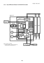
Page 149: ...al control remote controller to group header unit 2 Connection of weekly timer to sub remote controller is unavailable Main Sub master remote controller Up to 2 sets Weekly timer Key switch Function setup Key switch Power circuit EEPROM TA sensor TC sensor TCJ sensor HA Power supply 1Ø 220 240V 50Hz 1Ø 220V 60Hz Secondary battery Remote controller communication circuit Central control remote contr...

Page 150: ...o group header unit EEPROM TA sensor TC sensor TCJ sensor HA Central control remote controller Option 1 Start Alarm Ready Thermostat ON COOL HEAT FAN Remote controller A B setup BUS Communication circuit Fan motor control circuit AC synchronous signal input circuit Sensor part Power circuit LED Remote controller communication circuit CPU Central control communication circuit Driver L N L N Power s...

Page 151: ... the surrounding area If a gas stove or other appliance is being used extinguish the flames before proceeding If the flames are not extinguished they may ignite any oil mixed with the refrigerant gas 2 Do not use welding equipment in an airtight room Carbon monoxide poisoning may result if the room is not properly ventilated 3 Do not bring welding equipment near flammable objects Flames from the e...

Page 152: ...4 pcs 5 Take off 4 hooks of panel from rear side How to assemble the front panel 1 Push 3 center positions and 2 lower center positions of the air outlet and then hang the hanging hooks 4 pcs at the top side of the front panel to the rear plate 2 Tighten four screws Incomplete hanging or incomplete pushing may cause a dewdrops or generation of a fluttering sound 3 Push PUSH part under the front pa...

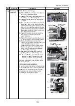
Page 153: ...t the same position before removing 9 Disengage the display unit by simply pushing at the top of the display unit 10 Remove the fixing screw that secures the electric parts box assembly LED assembly and remove the assembly Same as reassembly pace Addition of the following cautions Cautions in reassembling Mount the electric parts box to the main unit in the reverse order to the removing procedure ...

Page 154: ...me Procedures Remarks louver 1 Remove shaft of the horizontal louver from the back body First remove the left shaft and then remove other shafts while sliding the horizontal louver leftward Horizontal FILE NO SVM 14077 ...

Page 155: ... the main unit 3 Remove 2 fixing screws at the left side of the end plate of the heat exchanger Remarks 4 Remove 2 fixing screws on the heat exchager fixing holder to separate the heat exchager from the back body AP0243 to AP0153 5 Remove 4 fixing screws on the heat exchager fixing holder to separate the heat exchager from the back body AP0123 to AP0073 AP0243 to AP0153 AP0123 to AP0073 T FILE NO ...

Page 156: ... Remove the 2 screws used to secure the bearing base 3 Remove the bearing base Remarks Bearing base Bearing 2 screws Caution at assembling If the bearing is out from the housing push it into the specified position and then incorporate it in the main body U S FILE NO SVM 14077 ...

Page 157: ...screw of the cross flow fan 3 Remove 2 fixing screws of the motor cover and them remove the motor cover 4 Remove 2 more fixing screws of the motor band and remove the motor band Remarks 5 Pull the fan motor outward Set screw 2 screws on motor cover 2 screws on motor band V S FILE NO SVM 14077 ...

Page 158: ...g 5 mm from wall of rear plate of the main unit Holding the set screw install the cross flow fan so that U groove of the fan motor comes to the mounting hole of the set screw Perform positioning of the fan motor as follows When assembling the fan motor the fan motor must be installed in such a way that the fan motor leads will be taken out is positioned at the bottom front After assembling the 2 f...

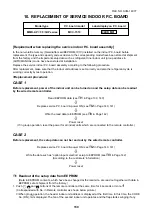
Page 159: ...H2 in Page 140 141 ò Write the read data to EEPROM see H3 in Page 142 ò Power reset If in group operation reset the power for all indoor units which are connected to the remote controller CASE 2 Before replacement the setup data can not be read out by the wired remote controller Replace service P C board power ON see H2 in Page 140 141 ò Write the data such as option input selection setup to EEPRO...

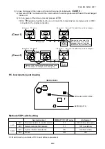
Page 160: ...DIP switch on the former P C board should be reflected on the service P C board Refer to the following table about DIP switch setting and drawing of P C board parts layout 2 It is necessary to set Indoor unit to be exchanged Remote controller 1 1 Based upon the system configuration turn on power of the indoor unit with one of the following items 1 Single Individual operation Turn on power of the i...

Page 161: ...sistor for central control Remote controller A B selection Custom Multi model selection No use MMK AP 3HP series 1 1 ON OFF At shipment OFF Without terminator OFF A selection ON Multi model OFF A B A B A B Indoor unit P C board Remote controller Group wire Group wire Case 1 Remove the group wire of the terminal blocks A and B of the changed indoor unit and then install the remote controller only R...

Page 162: ...ons set to the CODE No DN 2 Setup of lighting time of filter sign 6 The contents of the displayed setup data in this time should be agreed with the contents in the previous memorandum in H1 1 If data disagree change the displayed setup data to that in the previous memorandum by the timer time buttons and then push SET button OK when the display goes on 2 There is nothing to do when data agrees 7 U...

Page 163: ...from power cut Option input selection CN80 Thermo output selection T10 S Input selection T10 Q Sensor selection Timer set Wired remote controller Louver selection of cooling Memo Be sure to set as 0008 At shipment 0001 150 hour 0000 Standard 0099 Unfixed 0002 2 C 0000 Standard 0001 No auto mode Automatic selection by cooling heating connected outdoor unit 0000 Heat pump 0008 High wall type Accordi...

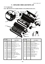
Page 164: ...T09045 Louver Horizontal 43T22011 Bearing Base 43T85587 Owner s Manual E1 232 43T85588 Owner s Manual TR1 43T15002 Display 43T00057 Panel Ass y 43T62032 Clamp Base Ass y 43T47044 Pipe Inlet 43T03018 Body Ass y Back 43T44539 Evaporator Ass y 43T39027 Plate Back 43T47043 Pipe Outlet Location Part No No 43T22312 Bearing Ass y 43T70313 Hose Drain 43T20016 Fan Ass y Cross Flow 43T49010 Pipe Shield 43T8...

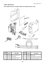
Page 165: ...rt No Description No 401 43T50012 Sensor Heat Exchanger 402 43T50304 Sensor Ass y 403 43T60078 Terminal Block 2P 20A 404 43T60079 Terminal Block 4P 1A Location Part No Description No 405 43T69320 Sensor TA 406 43T69081 P C Board Ass y MCC 1510 407 43T69082 P C Board Ass y MCC 5044 408 43T21397 Louver Motor MP24Z3T FILE NO SVM 14077 ...

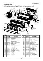
Page 166: ...Evaporator Ass y AP0243 43T44537 Evaporator Ass y AP0153 AP0183 43T47039 Pipe Outlet AP0243 43T47040 Pipe Outlet AP0153 AP0183 43T47041 Pipe Inlet AP0243 43T85587 Owner s Manual E1 232 43T85588 Owner s Manual TR1 43T15002 Display 43T00057 Panel Ass y 43T62032 Clamp Base Ass y 43T49045 Pipe Shield AP0243 Location Part No No 43T22312 Bearing Ass y 43T70313 Hose Drain 43T20016 Fan Ass y Cross Flow 43...

Page 167: ...rt No Description No 401 43T50012 Sensor Heat Exchanger 402 43T50304 Sensor Ass y 403 43T60078 Terminal Block 2P 20A 404 43T60079 Terminal Block 4P 1A Location Part No Description No 405 43T69320 Sensor TA 406 43T69081 P C Board Ass y MCC 1510 407 43T69082 P C Board Ass y MCC 5044 408 43T21397 Louver Motor MP24Z3T FILE NO SVM 14077 ...

Page 168: ...TOSHIBA CARRIER THAILAND CO LTD 144 9 MOO 5 BANGKADI INDUSTRIAL PARK TIVANON ROAD TAMBOL BANGKADI AMPHUR MUANG PATHUMTHANI 12000 THAILAND ...

Reviews: