background image

2-4

User’s Manual

The Grand Tour

Right side

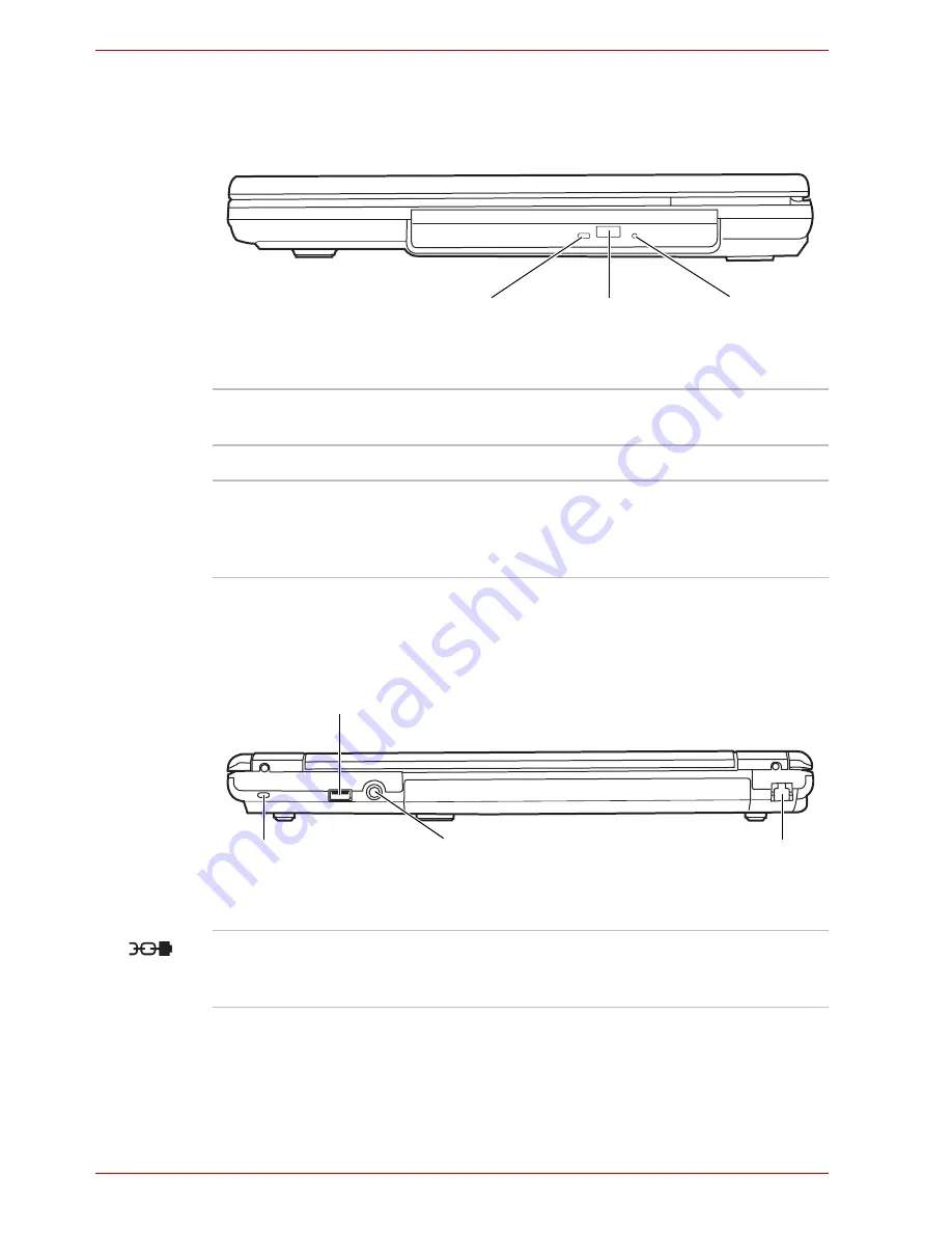
The following figure shows the computer's right side. 

The right side of the computer

Backside

The following figure shows the computer's back panel. 

The backside of the computer

Eject Button

ODD 

Indicator

Emergency 

Eject Hole 

ODD Indicator

The ODD indicator glows amber when the 

computer accesses the optical disc drive.

Eject Button

Press this button to open the ODD tray.

Emergency Eject 

Hole

In the event that the disc drive becomes 

inexplicably locked or stops responding press 

this button to force a manual ejection of the ODD 

tray.

Security Lock

DC IN 19V Jack

LAN Jack

USB Port

Security Lock

A security cable attaches to this port. The 

optional security cable anchors your computer to 

a desk or other large object to deter theft.

Summary of Contents for Satellite L30 Series

Page 1: ...TOSHIBA Satellite L30 Satellite Pro L30 Series User s Manual ...

Page 2: ...e this product to copy the copyrighted works or perform other actions Please note that you may infringe the owner s rights protected by the copyright laws if you use the screen mode switching functions e g Wide mode Wide Zoom mode etc of this product to display enlarged images video at coffee shops or hotels for the purposes of profits or providing these to the public Disclaimer This manual has be...

Page 3: ...comply with the limits for a Class B digital device pursuant to part 15 of the FCC rules These limits are designed to provide reasonable protection against harmful interference in a residential installation This equipment generates uses and can radiate radio frequency energy and if not installed and used in accordance with the instructions may cause harmful interference to radio communications How...

Page 4: ...ripherals complying with the FCC class B limits may be attached to this equipment Operation with non compliant peripherals or peripherals not recommended by TOSHIBA is likely to result in interference to radio and TV reception Shielded cables must be used between the external devices and the computer s external monitor port USB port serial port parallel port PS 2 mouse keyboard port and microphone...

Page 5: ...matériel brouileur du Canada Modem warning notice Conformity Statement The equipment has been approved to Council Decision 98 482 EC TBR 21 for pan European single terminal connection to the Public Switched Telephone Network PSTN However due to differences between the individual PSTNs provided in different countries regions the approval does not of itself give an unconditional assurance of success...

Page 6: ...uivalence Number REN of the modem which can vary For the REN of your modem refer to your modem s label The modem connects to the telephone line by means of a standard jack called the USOC RJ11C Type of service Your modem is designed to be used on standard device telephone lines Connection to telephone company provided coin service central office implemented systems is prohibited Connection to part...

Page 7: ...he first page of the transmission the date and time it is sent and an identification of the business other entity or individual sending the message and the telephone number of the sending machine or such business other entity or individual In order to program this information into your fax modem you should complete the setup of your fax software before sending messages Instructions for IC CS 03 ce...

Page 8: ...gion selection is set to Australia The use of other country region setting while the modem is attached to the Australian PSTN would result in you modem being operated in a non compliant manner To verify that the country region is correctly set enter the command ATI9 which displays the currently active setting To set the country region permanently to Australia enter the following command sequence A...

Page 9: ...te a nuisance to other Telecom customers Some parameters required for compliance with Telecom s PTC Specifications are dependent on the equipment PC associated with this modem The associated equipment shall be set to operate within the following limits for compliance with Telecom Specifications a There shall be no more than 10 call attempts to the same number within any 30 minute period for any si...

Page 10: ...rt a fault if the phone performance is impaired It is recommended that this equipment be disconnected from the Telecom line during electrical storms When relocating the equipment always disconnect the Telecom line connection before the power connection and reconnect the power first This equipment may not be compatible with Telecom Distinctive Alert cadences and services such as FaxAbility NOTE THA...

Page 11: ...ember states The symbol indicates that this product may not be treated as household waste Please ensure this product is properly disposed as inappropriate waste handling of this product may cause potential hazards to the environment and human health For more detailed information about recycling of this product please contact your local city office your household waste disposal service or the shop ...

Page 12: ...t please read this instruction manual carefully and retain for future reference Should the unit ever require maintenance contact an authorized service location Use of controls adjustments or the performance of procedures other than those specified may result in hazardous radiation exposure To prevent direct exposure to the laser beam do not try to open the enclosure ...

Page 13: ... product please read this instruction manual carefully and retain for future reference Should the unit ever require maintenance contact an authorized service location Use of controls adjustments or the performance of procedures other than those specified may result in hazardous radiation exposure To prevent direct exposure to the laser beam do not try to open the enclosure ...

Page 14: ... use of this product please read this instruction manual carefully and retain for future reference Should the unit ever require maintenance contact an authorized service location Use of controls adjustments or the performance of procedures other than those specified may result in hazardous radiation exposure To prevent direct exposure to the laser beam do not try to open the enclosure ...

Page 15: ...per use of this product please read this instruction manual carefully and retain for future reference Should the unit ever require maintenance contact an authorized service location Use of controls adjustments or the performance of procedures other than those specified may result in hazardous radiation exposure To prevent direct exposure to the laser beam do not try to open the enclosure ...

Page 16: ... this product please read this instruction manual carefully and retain for future reference Should the unit ever require maintenance contact an authorized service location Use of controls adjustments or the performance of procedures other than those specified may result in hazardous radiation exposure To prevent direct exposure to the laser beam do not try to open the enclosure ...

Page 17: ...die Bedienungsanleitung sorgfältig durch und bewahren diese bitte als Referenz auf Falls Probleme mit diesem Modell auftreten benachrichtigen Sie bitte die nächste autorisierte Service Vertretung Um einen direkten Kontakt mit dem Laserstrahl zu vermeiden darf das Gerät nicht geöffnet werden ADVARSEL Denne mærking er anbragt udvendigt på apparatet og indikerer at apparatet arbejder med laserstråler...

Page 18: ...in joka lähetää näkymätöntä silmilie vaarallista lasersäteilyä CAUTION USE OF CONTROLS OR ADJUSTMENTS OR PERFORMANCE OF PROCEDURES OTHER THAN THOSE SPECIFIED IN THE OWNER S MANUAL MAY RESULT IN HAZARDOUS RADIATION EXPOSURE VORSICHT DIE VERWENDUNG VON ANDEREN STEURUNGEN ODER EINSTELLUNGEN ODER DAS DURCHFÜHREN VON ANDEREN VORGÄNGEN ALS IN DER BEDIENUNGSANLEITUNG BESCHRIEBEN KÖNNEN GEFÄHRLICHE STRAHL...

Page 19: ...es information on workspace design posture and lighting that can help reduce physical stress Heat warning Avoid prolonged physical contact with the computer If the computer is used for long periods its surface can become very warm While the temperature will not feel hot to the touch if you maintain physical contact with the computer for a long time if you rest the computer on your lap or if you ke...

Page 20: ...tain multimedia games or videos with special effects use of standard telephone lines or low speed network connections use of complex modelling software such as high end computer aided design applications use of the computer in areas with low air pressure high altitude 1 000 meters or 3 280 feet above sea level use of the computer at temperatures outside the range of 5 C to 35 C 41 F to 95 F or 25 ...

Page 21: ...l commercial and light industry environments For example the following environments are not approved Industrial Environments environments with a main voltage 230V Medical Environments Automotive Environments Aircraft Environments Any consequences resulting from the use of this product in working environments that are not approved are not the responsibility of TOSHIBA The consequences of the use of...

Page 22: ...ommittees of scientists who continually review and interpret the extensive research literature In some situations or environments the use of Wireless LAN may be restricted by the proprietor of the building or responsible representatives of the organisation These situations may for example include Using the Wireless LAN equipment on board of aeroplanes or In any other environment where the risk of ...

Page 23: ... related to our company we do not take any responsibility Usage Restrictions Do not use the Wireless Products for controlling the following equipment Equipment directly linked with human life corresponding to the following Medical equipment such as life support systems equipment used in operations etc Exhaust systems for gases such as poisonous gas etc and exhaust systems for smoke Equipment that ...

Page 24: ...ON the Wireless Communication switch in aircraft or in places that generate or can generate radio interference Radio waves can potentially affect them causing an accident due to malfunction Monitor possible radio interference or other troubles to other equipment while the product is used If any effect is caused turn OFF the Wireless Communication switch Otherwise radio waves can potentially affect...

Page 25: ...xxxiii Messages xxxiii Chapter 1 Introduction Equipment checklist 1 1 Hardware 1 1 Software 1 2 Features 1 3 Special features 1 8 Utilities 1 12 Options 1 14 Chapter 2 The Grand Tour Front with the display closed 2 1 Left side 2 2 Right side 2 4 Backside 2 4 Underside 2 5 Front with the display open 2 6 Fixed optical media drives 2 7 Region codes for DVD drive and media 2 7 Writable discs 2 8 CDs ...

Page 26: ... 3 11 Restarting the computer 3 12 Create Optical Recovery Discs Depends on the model you purchased 3 13 Restoring the preinstalled software from the Recovery HDD Depends on the model you purchased 3 13 Restoring the preinstalled software from Recovery Media 3 14 Chapter 4 Operating Basics Using the TouchPad 4 1 Using the optical media drive 4 2 Loading discs 4 3 Removing discs 4 6 Writing CDs wit...

Page 27: ...yboard Typewriter keys 5 1 F1 F12 function keys 5 2 Soft keys Fn key combinations 5 2 Emulating keys on enhanced keyboard 5 2 Hot keys 5 3 Fn Sticky key Depends on the model you purchased 5 5 Windows special keys 5 6 Keypad overlay 5 6 Turning on the overlays 5 6 Temporarily using normal keyboard overlay on 5 7 Generating ASCII characters 5 7 Chapter 6 Power and Power Up Modes Power conditions 6 1...

Page 28: ...up 7 1 HW Setup Window 7 1 Chapter 8 Optional Devices PC card 8 2 Inserting a PC Card 8 2 Removing a PC Card 8 3 Memory expansion 8 4 Installing a memory module 8 5 Removing a memory module 8 6 Additional battery pack 8 7 Additional AC adaptor 8 8 External monitor 8 8 Security lock 8 9 Chapter 9 Troubleshooting Problem solving process 9 1 Preliminary checklist 9 2 Analyzing the problem 9 2 Hardwar...

Page 29: ...Monitor 9 13 Modem 9 13 LAN 9 14 Wireless LAN 9 14 TOSHIBA support 9 15 Before you call 9 15 Where to write 9 15 Appendix A Specifications Appendix B Display Controller and Modes Appendix C Wireless LAN Appendix D AC Power Cord and Connectors Glossary Index ...

Page 30: ...xxx User s Manual Table of Contents ...

Page 31: ...essory devices Then read Getting Started for step by step instructions on setting up your computer If you are an experienced computer user please continue reading the preface to learn how this manual is organized then become acquainted with this manual by browsing through its pages Be sure to look over the Specifications section of the Introduction to learn about features that are uncommon or uniq...

Page 32: ...mputer doesn t seem to be working properly The Appendices provide technical information about your computer The Glossary defines general computer terminology and includes a list of acronyms used in the text The Index quickly directs you to the information contained in this manual Conventions This manual uses the following formats to describe identify and highlight terms and operating procedures Ab...

Page 33: ...n below ABC When procedures require an action such as clicking an icon or entering text the icon s name or the text you are to type in is represented in the type face you see to the left ABC Names of windows or icons or text generated by the computer that appears on its display screen is presented in the type face you see to the left Pay attention A caution informs you that improper use of equipme...

Page 34: ...xxxiv User s Manual Preface ...

Page 35: ...are Check to make sure you have all the following items TOSHIBA Satellite L30 Satellite Pro L30 Series Portable Personal Computer Universal AC adaptor and power cord Modular cable for modem optional part dependant on model purchased Some of the features described in this manual may not function properly if you use an operating system that was not pre installed by TOSHIBA It is necessary to install...

Page 36: ...ls Sound driver for Windows DVD Video Player LAN driver Pointing device driver TOSHIBA Hotkey Utility TOSHIBA User s Manual TOSHIBA Assist TOSHIBA ConfigFree TOSHIBA Touch and Launch TOSHIBA Power Saver Utility TOSHIBA TouchPad On Off Utility TOSHIBA PC Diagnostic Tool TOSHIBA Zooming Utility Other software may preinstalled dependant on the model purchased indicates an optional software part that ...

Page 37: ...rably less and will vary by model and system configuration Slots Up to two 1024 MB memory modules can be installed in the memory slot for a maximum of 2 GB system memory total Video RAM Maximum 256 MB of RAM is provided for video display 1GB or more of system memory is required Battery Pack Your computer is powered by a rechargeable lithium ion battery pack RTC Battery The internal RTC battery bac...

Page 38: ...ailable in three sizes 40 0 billion bytes 37 26 GB 60 0 billion bytes 55 89 GB 80 0 billion bytes 74 53 GB Other hard disk drives may introduced in the future Computers in this series can be configured with a fixed optical media drive The available optical media drives are described below DVD ROM CD R RW Drive Some models are equipped with a full size DVD ROM CD R RW drive module that lets you run...

Page 39: ...ssion CD ROM Mode 1 Mode 2 CD ROM XA Mode 2 Form 1 Form 2 Enhanced CD CD Extra Built In 14 1 WXGA or 15 4 WXGA TFT non glare 16 M colors with the following resolution 1280 horizontal 800 vertical pixels Graphics Controller Graphics controller maximizes display performance Refer to Display Controller and Modes section in Appendix B Display Controller and Modes for more information Built In 84 keys ...

Page 40: ...ternal microphone and headphones Headphone Jack This jack outputs analog audio signals Microphone Jack A 3 5 mm mini microphone jack enables connection of a three conductor mini jack for monaural microphone input Modem The internal modem feature is not available on all models Where presents it provides capability for data and fax communication It supports V 90 V 92 The speed of data transfer and f...

Page 41: ... Management Wired Equivalent Privacy WEP data encryption based on 128 bit encryption algorithm Advanced Encryption Standard AES data encryption based on 128 bit encryption algorithm Operating System Windows XP Home Edition Windows XP Professional or Windows XP Starter Edition operating system and TOSHIBA Utilities and drivers pre installed on the hard disk Refer to the Software section at the fron...

Page 42: ...zed access to your computer To register a supervisor password double click the TOSHIBA Assist on your desktop select the SECURE tab and start the Supervisor password utility To set a user password select the SECURE tab on TOSHIBA Assist then start User password utility In the Password tab you can register a user password Instant Security The hot key function Fn F1 blanks the screen and disables th...

Page 43: ... hardware access for a specified time To specify the time On Windows XP Home Edition Professional model Click Start Control Panel Performance and Maintenance TOSHIBA Power Saver On the Basic Setup tab you can specify the time for either System standby or System hibernation settings On Windows XP Starter Edition model Click Start Control Panel Performance and Maintenance Power Options On the Power ...

Page 44: ...XP Home Edition Professional model Click Start Control Panel Performance and Maintenance TOSHIBA Power Saver On the Setup Action tab you can specify the setting for When I close the lid On Windows XP Starter Edition model Click Start Control Panel Performance and Maintenance Power Options and Acvanced tab Low Battery Automatic Hibernation When battery power is exhausted to the point that computer ...

Page 45: ...g the CPU processing speed Battery optimized Lowers the CPU processing speed first then if necessary turns on the fan Hibernation This feature lets you turn off the power without exiting from your software The contents of main memory are saved to the hard disk so that when you turn on the power again you can continue working right where you left off Refer to the Turning off the power section in Ch...

Page 46: ...the way you work with your computer and the peripherals you use To start the utility double click the TOSHIBA Assist on your desktop select OPTIMIZE tab and click TOSHIBA HW Settings DVD Video Player Depends on the model you purchased The DVD Video Player is used to play DVD Video It has an on screen interface and functions Click start point to All Programs point to InterVideo WinDVD then click In...

Page 47: ...communication networks To run ConfigFree click start select All Programs followed by TOSHIBA followed by Networking and then click ConfigFree TOSHIBA TouchPad On Off Utility Pressing Fn F9 enables or disables the TouchPad function When you press these hot keys the current setting will change and be displayed as an icon TOSHIBA Touch and Launch Depends on the model you purchased TOSHIBA Touch and L...

Page 48: ... memory modules can be installed in this computer Use only DDRII 533MHz compatible memory modules See your TOSHIBA dealer for details Battery pack An additional battery pack can be purchased from your TOSHIBA dealer Use it as a spare or replacement AC Adaptor If you use your computer at more than one site frequently it may be convenient to purchase an additional AC adaptor for each site so you wil...

Page 49: ...DD LEDs Headphone Jack Speaker Wireless Activity LED Microphone Jack Speakers The speakers emit sound generated by your software as well as audio alarms such as low battery condition generated by the system Power The Power indicator glows green when the computer is on If you select Standby from Turn Off Computer this indicator flashes orange one second on two seconds off while the computer enters ...

Page 50: ... off in airplanes and hospitals Check the wireless activity indicator It will stop glowing when the wireless communication function is off Wireless Activity LED Shows you Wireless LAN activity and whether the Wireless LAN feature is engaged or not Display Latch This latch secures the LCD panel in its closed position Slide the latch to open the display Headphone Jack This jack outputs analog audio ...

Page 51: ...ta transfer speeds 40 times faster than the USB 1 1 standard The ports also support USB 1 1 Keep foreign objects out of the USB connectors A pin or similar object can damage the computer s circuitry Operation of all functions of all USB devices has not been confirmed As such some untested third party devices may not function properly Modem Jack The modem jack allows you to use a modular cable to c...

Page 52: ...ODD indicator glows amber when the computer accesses the optical disc drive Eject Button Press this button to open the ODD tray Emergency Eject Hole In the event that the disc drive becomes inexplicably locked or stops responding press this button to force a manual ejection of the ODD tray Security Lock DC IN 19V Jack LAN Jack USB Port Security Lock A security cable attaches to this port The optio...

Page 53: ...lar object can damage the computer s circuitry Operation of all functions of all USB devices has not been confirmed As such some untested third party devices may not function properly DC IN 19V Jack The AC adaptor connects to this socket Use only the model of AC adaptor that comes with the computer Using the wrong adaptor can damage your computer LAN Jack This jack lets you connect to a LAN The ad...

Page 54: ...rs the computer when the AC adaptor is not connected For detailed information on the battery pack refer to Chapter 6 Power and Power Up Modes Battery Release Latch 2 Slide and hold this latch to release the battery pack for removal For detailed information on removing the battery packs refer to Chapter 6 Power and Power Up Modes Cooling Vents Cooling vents help prevent the CPU from overheating Mem...

Page 55: ...from Stand by mode Display Screen The LCD displays high contrast text and graphics Refer to Appendix B Display Controller and Modes When the computer operates on the AC adaptor the display screen s image will be somewhat brighter than when it operates on battery power The lower brightness level is intended to save battery power TouchPad A TouchPad located in the centre of the palm rest is used to ...

Page 56: ... RW discs or high speed 4 to 10 speed discs The write speed of the ultra speed CD RW discs Ultra speed is available on the DVD ROM CD R RW drive only is a maximum of 24 speed Formats The drives support the following formats DVD ROM CD DA Photo CDTM single multi session CD ROM XA Mode 2 Form1 Form2 CD R DVD Video CD Text CD ROM Mode 1 Mode 2 Enhanced CD CD EXTRA CD RW Not available on the CD ROM dr...

Page 57: ... automatically adjust to any voltage from 100 to 240 volts and to a frequency of either 50 or 60 hertz enabling you to use the computer in almost any country region To recharge the battery simply connect the AC adaptor to a power source and the computer Refer to Chapter 6 Power and Power Up Modes for details The AC adaptor The read speed is slower at the centre of a disc and faster at the outer ed...

Page 58: ...r that is compatible Use of any incompatible adaptor or other types of AC Adaptors may have a different voltage which could cause damage to your computer computer failure and or possible data loss Toshiba assumes no liability for any damage computer failure and or data loss caused by use of an incompatible adaptor Use only the AC adaptor supplied as an accessory Other AC adaptors have different vo...

Page 59: ...work space for your health and safety Installing the battery pack Connecting the AC adaptor Opening the display Turning on the power Windows XP setup Turning off the power Restarting the computer Restoring the preinstalled software Be sure also to read the Safety Instruction Manual This guide which is included with the computer explains product liability All users should be sure to read the sectio...

Page 60: ...ly accessible The temperature should be 5 to 35 degrees Centigrade 41 to 95 degrees Fahrenheit and the relative humidity should be 20 to 80 percent Avoid areas where rapid or extreme changes in temperature or humidity may occur Keep the computer free of dust moisture and exposure to direct sunlight Keep the computer away from heat sources such as electric heaters Do not use the computer near liqui...

Page 61: ...e computer Seating and posture The height of your chair in relation to the computer and keyboard as well as the support it gives your body are primary factors in reducing work strain Refer to the following tips and to the following figure Posture and positioning of the computer Place your chair so that the keyboard is at or slightly below the level of your elbow You should be able to type comforta...

Page 62: ...ess and improve your efficiency Sit in a relaxed posture Good positioning of your chair and equipment as described earlier can reduce tension in your shoulders or neck and ease back strain Vary your posture frequently Occasionally stand up and stretch or exercise briefly Exercise and stretch your wrists and hands a number of times during the day Frequently look away from the computer and focus you...

Page 63: ...ng the battery pack The battery pack is a lithium ion battery which can explode if not properly replaced used handled or disposed of Dispose of the battery as required by local ordinances or regulations Use only batteries recommended by TOSHIBA as replacements Do not touch the latch while holding the computer Or you may get injured by the dropped battery by unintentional release of the latch Pleas...

Page 64: ...r supplied as an accessory Other AC adaptors have different voltage and terminal polarities and use of them may produce heat and smoke or even result in fire or rupture Use only the AC adaptor supplied with your computer or an equivalent adaptor that is compatible Use of any incompatible adaptor could damage your computer TOSHIBA assumes no liability for any damage caused by use of an incompatible...

Page 65: ...e wall outlet Opening the display The display panel can be rotated in a wide range of angles for optimal viewing 1 Slide the display latch on the front of the computer to the right 2 Lift the panel up and adjust it to the best viewing angle for you Opening the display Use reasonable care when opening and closing the display panel Opening it vigorously or slamming it shut could damage the computer ...

Page 66: ... power Windows XP setup When you first turn on the power the computer s initial screen is the Microsoft Windows XP Startup Screen Logo Follow the on screen directions After you turn on the power for the first time do not turn it off until you have set up the operating system Refer to the section Windows XP setup Be sure to read the Windows End User License Agreement display carefully ...

Page 67: ... hard disk when the computer is turned off The next time the computer is turned on the previous state is restored The hibernation feature does not save the status of peripheral devices Make sure the Built in HDD ODD indicators are off If you turn off the power while a disk disc is being accessed you can lose data or damage the disk disc Do not turn the computer or devices back on immediately Wait ...

Page 68: ...ibernation Mode The computer will enter Hibernation mode automatically when you press the power button or close the Display Screen First however make the appropriate settings according to the steps below 1 Open the Control Panel 2 Open Performance and Maintenance and open Power Options 3 Select the Hibernate tab in the Power Options Properties select the Enable hibernation check box and click the ...

Page 69: ...diately Wait a moment to let all capacitors fully discharge When the AC adaptor is connected the computer will go into Standby Mode according to the settings in the TOSHIBA Power Saver To restore operation from Standby Mode press the power button or press any key The latter action works only if Wake up on Keyboard is enabled in HW Setup If the computer automatically enters Standby Mode while a net...

Page 70: ...estarting the computer Certain conditions require that you reset the system For example if You change certain computer settings An error occurs and the computer does not respond to your keyboard commands There are three ways to reset the computer system 1 Click start then click Turn off computer From the Turn off computer menu select Restart 2 Press Ctrl Alt Del to display the Windows Task Manager...

Page 71: ...ased About 2 5 GB of hard disk space is reserved for the recovery partition When re setting up your hard disk do not change delete or add partitions in a manner other than specified in the manual Otherwise space for software may be destroyed In addition if you use a third party partitioning program to reconfigure partitions on your hard disk it may become impossible to re setup your computer 1 Tur...

Page 72: ...y Media in the optional optical media drive and turn off the computer s power 2 Hold down the F12 key and turn on the power When In Touch with Tomorrow TOSHIBA appears release the F12 key 3 Use the upper or lower cursor key to select the CD DVD in the display menu For details refer to the Boot Priority section in Chapter 7 HW Setup Depends on the model you purchased 4 A menu appears Follow the on ...

Page 73: ...sing the TouchPad To use the TouchPad simply touch and move your finger tip across it in the direction you want the on screen pointer to go TouchPad and TouchPad control buttons Two buttons below the keyboard are used like the buttons on a mouse pointer Press the left button to select a menu item or to manipulate text or graphics designated by the pointer Press the right button to display a menu o...

Page 74: ...puter is accessing a CD ROM an indicator on the drive glows If you have a DVD ROM CD R RW drive refer also to the Writing CDs with the DVD ROM CD R RW drive section for precautions on writing to CDs DVDs Do not press on the TouchPad too hard or press a sharp object such as a ball point pen against the TouchPad The TouchPad could be damaged Click Tap the TouchPad once Double click Tap the TouchPad ...

Page 75: ...open the drawer slightly Pressing the eject button b Pressing the eject button will not open the drawer when the disc drive s power is off If the power is off you can open the drawer by inserting a slender object about 15 mm such as a straightened paper clip into the eject hole just to the right of the eject button Manual release with the eject hole Eject Button ...

Page 76: ...4 4 User s Manual Operating Basics 2 Grasp the drawer gently and pull until it is fully opened Pulling the drawer open 3 Place the disc label side up in the drawer Inserting a disc ...

Page 77: ...ll extend slightly over the disc tray Therefore you will need to turn the disc at an angle when you place it in the tray After seating the disc however make sure it lies flat as shown in the figure above Do not touch the laser lens Doing so could cause misalignment Keep foreign matter from entering the drive Check the back edge of the tray to make sure it carries no debris before closing the drive...

Page 78: ...he drawer to close it Press gently until it locks into place Do not press the eject button while the computer is accessing the disc drive Wait for the optical media drive indicator to go out before you open the drawer Also if the disc is spinning when you open the drawer wait for it to stop before you remove it When the drawer pops open slightly wait a moment to make sure the disc has stopped spin...

Page 79: ...R and CD RW media Media quality can affect write or rewrite success rates For the special media listed below the following manufacturers are recommended High Speed CD RW MITSUBISHI Chemical Corporation Ricoh Co Ltd Ultra Speed CD RW MITSUBISHI Chemical Corporation TOSHIBA has confirmed the operation of CD R and CD RW media of the manufacturers above Operation of other media cannot be guaranteed CD...

Page 80: ...XP operating system Operate the computer for any other function including use of a mouse or TouchPad closing opening the LCD panel Start a communication application such as a modem Apply impact or vibration to the PC Install remove or connect external devices including the following PC Card USB devices external display optical digital devices Open the optical media drive If the media is poor in qu...

Page 81: ...e Start menu and then selecting All Programs DVD RAM DVD RAM Driver and DVDForm sequentially Do not use any discs that have been formatted with packet writing software other than TOSHIBA Direct Disc Writer Similarly do not use any discs that have been formatted with TOSHIBA Direct Disc Writer with any packet writing software other than TOSHIBA Direct Disc Writer When using a disc you are not famil...

Page 82: ...ume Control utility lets you control the audio volume in Windows for both playback and recording To launch Volume Control for playback click start point to All Programs point to Accessories point to Entertainment and click Volume Control To launch Recording Control click Options point to Properties choose Recording and click OK If Recording cannot be chosen choose Mixer device before To view detai...

Page 83: ...heck will appear next to the currently selected region and telephony location 3 Select a region from the region menu or a telephony location from the sub menu When you click a region it becomes the modem s region selection and the New Location for telephony will be set automatically When you select a telephony location the corresponding region is automatically selected and it becomes the modem s c...

Page 84: ...t for region selection A submenu appears displaying location information for telephony Open dialog box if the modem and Telephony Current Location region code do not match A warning dialog box is displayed if current settings for region code and telephony location are incorrect Modem Selection If the computer cannot recognize the internal modem a dialog box is displayed Select the COM port for you...

Page 85: ...ect the end of the modular cable with the core to the computer In case of a lightning storm unplug the modem cable from the telephone jack Do not connect the modem to a digital telephone line A digital line will damage the modem Do not pull on the cable or move the computer while the cable is connected If you use a storage device such as an optical drive or hard disk drive connected to a 16 bit PC...

Page 86: ... channels Card Power Management Wired Equivalent Privacy WEP data encryption based on the 128 bit encryption algorithm Advanced Encryption Standard AES data encryption based on 128 bit encryption algorithm Security Be sure to enable the encryption function otherwise you may expose your computer to illegal access by an outsider across the Wireless LAN which may cause intrusion eavesdropping and the...

Page 87: ...BASE T and Fast Ethernet LAN 100 megabits per second 100BASE TX This section describes how to connect disconnect to a LAN LAN cable types If you are using Fast Ethernet LAN 100 megabits per second 100BASE TX be sure to connect with a CAT5 cable or higher You cannot use a CAT3 cable If you are using Ethernet LAN 10 megabits per second 10BASE T you can connect with a CAT3 cable or higher Indicator s...

Page 88: ...with your LAN administrator before disconnecting from the hub Cleaning the computer To help ensure long trouble free operation keep the computer free of dust and use care with liquids around the computer Be careful not to spill liquids into the computer If the computer does get wet turn the power off immediately and let the computer dry completely before you turn it on again Clean the computer usi...

Page 89: ...on the computer If a CD DVD is in the drive remove it Also make sure the drawer is securely closed Turn off the power to the computer Disconnect the AC adaptor and all peripherals before moving the computer Close the display Do not pick up the computer by its display panel Use the carrying case when transporting the computer When carrying your computer be sure to hold it securely so that it does n...

Page 90: ...4 18 User s Manual Operating Basics ...

Page 91: ...per and lower case letters numbers punctuation marks and special symbols that appear on the screen There are some differences however between using a typewriter and using a computer keyboard Letters and numbers produced in computer text vary in width Spaces which are created by a space character may also vary depending on line justification and other factors The lowercase l el and the number 1 one...

Page 92: ...ey combinations that enable disable or configure specific features Emulating keys on enhanced keyboard A 101 key enhanced keyboard layout The keyboard is designed to provide all the features of the 101 key enhanced keyboard shown in figure above The 101 102 key enhanced keyboard has a numeric keypad and scroll lock key It also has additional Enter and Ctrl keys to the right of the main keyboard Si...

Page 93: ...d original settings press any key or press the TouchPad If a screensaver password is registered a dialog box will appear Enter the screensaver password and click OK If no password is set the screen will be restored when you press any key or press the TouchPad Power save mode On Windows XP Home Edition Professional pressing Fn F2 changes the power save mode if you press Fn F2 in a Windows environme...

Page 94: ...ases the display brightness in decrements When you press these hot keys the current setting will be displayed for two seconds by an icon LCD Display Brightness Pressing Fn F7 increases the display brightness in increments When you press these hot keys the current setting will be displayed for two seconds by a pop up icon Wireless setting Pressing Fn F8 allows you to switch between active wireless ...

Page 95: ...n to decrease the sound volume After you press this hot key an icon showing the new setting will be displayed for two seconds Volume increase Press Fn Up to increase the sound volume After you press this hot key an icon showing the new setting will be displayed for two seconds Fn Sticky key Depends on the model you purchased You can use the TOSHIBA Accessibility Utility to make the Fn key sticky t...

Page 96: ...yboard does not have an independent numeric keypad but its numeric keypad overlay functions like one The keys in the centre of the keyboard with gray letters make up the numeric keypad overlay The overlay provides the same functions as the numeric keypad on the 101 102 key enhanced keyboard described previously Turning on the overlays The numeric keypad overlay can be used for numeric data input N...

Page 97: ... character key 3 Release Fn to continue using the overlay Generating ASCII characters Not all ASCII characters can be generated using normal keyboard operation But you can generate these characters using their ASCII codes With the overlay on 1 Hold down Alt 2 Using the overlay keys type the ASCII code 3 Release Alt and the ASCII character appears on the display screen With the overlay off 1 Hold d...

Page 98: ...5 8 User s Manual The Keyboard ...

Page 99: ...battery is installed and what the charge level is for the battery Table Power conditions Power on Power off no operation Universal AC adaptor connected Battery fully charged Operates LED Battery green LED Battery green Battery partially charged or no charge Operates Quick Charge LED Battery orange Quick charge LED Battery orange No battery installed Operates No charge LED Battery off No charge LED...

Page 100: ...the AC adaptor is connected and charging the battery Green Indicates the AC adaptor is connected and the battery is fully charged No light Under any other conditions the indicator does not light If the battery becomes too hot while it is being charged the charge will stop and the battery indicator will go out When the battery s temperature falls to a normal range charge will resume This occurs whe...

Page 101: ...xtending battery life in this chapter for procedures If the computer is continuously operated on AC power through an AC adaptor for an extended period more than a month the battery may fail to retain a charge It may not function efficiently over the expected life of the battery and the Battery indicator may not indicate a low battery condition The battery pack is a lithium ion battery which can ex...

Page 102: ...the date in System Date 3 Set the time in System Time 4 Press F10 key Confirmation message will appear Press Enter key BIOS setup will terminate and the computer will be rebooted The computer s RTC battery is a lithium ion battery and should be replaced only by your dealer or by a TOSHIBA service representative The battery can explode if not properly replaced used handled or disposed of Dispose of...

Page 103: ...ck will overheat and ignite Leakage of caustic alkaline solution or other electrolytic substances will cause fire or injury possibly resulting in death or serious injury 3 Never short circuit the battery pack by contacting the terminals with a metal object A short circuit can cause fire or otherwise damage the battery pack and possibly cause injury To avoid accidental short circuit always wrap the...

Page 104: ... checked by a TOSHIBA service provider It might generate smoke or fire or the battery pack might rupture 3 Make sure the battery is securely installed in the computer before attempting to charge the battery pack Improper installation could generate smoke or fire or cause the battery pack to rupture 4 Keep the battery pack out of reach of infants and children It can cause injury Caution 1 Never con...

Page 105: ... for more than a few hours at a time Continuing to charge a fully charged battery pack can damage the battery Charging the batteries When the power in the battery pack becomes low the Battery indicator flashes orange indicating that only a few minutes of battery power remain If you continue to use the computer while the Battery indicator flashes the computer enables Hibernation Mode so you don t l...

Page 106: ...e A cool battery is installed in a warm computer In such case follow the steps below 1 Fully discharge the battery by leaving it in the computer with the power on until the power automatically shuts off 2 Plug in the AC adaptor 3 Charge the battery until the Battery indicator glows green Repeat these steps two or three times until the battery recovers normal capacity Charging time hours Battery ty...

Page 107: ...ently turning the computer off and on Where you store your programs and data Closing the display when you are not using the keyboard saves power Operating time decreases at low temperatures The condition of the battery terminals Make sure the battery terminals stay clean by wiping them with a clean dry cloth before installing the battery pack Wait at least 16 seconds after turning on the computer ...

Page 108: ...ome other warning to indicate a low battery go to step 4 4 Connect the AC adaptor to the computer and the power cord to a power outlet The Battery indicator should glow orange to indicate that the battery pack is being charged If the Battery indicator does not glow power is not being supplied Check the connections for the AC adaptor and power cord 5 Charge the battery pack until the Battery indica...

Page 109: ...d to the computer 4 Turn the computer upside down 5 Slide and hold the battery release latch 2 to free the battery pack after moving the battery release lock 1 into its unlock position then slide the battery pack out of the computer Releasing the battery pack When handling battery packs do not short circuit the terminals Also do not drop hit or otherwise apply impact do not scratch or break the ca...

Page 110: ...ars 2 Enter the password 3 Press Enter The battery pack is a lithium ion battery which can explode if not properly replaced used handled or disposed of Dispose of the battery as required by local ordinances or regulations Use only batteries recommended by TOSHIBA as replacements Do not touch the latch while holding the computer Or you may get injured by the dropped battery by unintentional release...

Page 111: ... 5 The Keyboard for details Panel power off on You can set up your computer so that power turns off automatically when you close the display panel When you open the panel power turns on in Standby Mode or Hibernation Mode but not in boot mode System Auto Off This feature turns the system off automatically if it is not used for a set duration The system shuts down in Standby Mode or Hibernation Mod...

Page 112: ...6 14 User s Manual Power and Power Up Modes ...

Page 113: ...and Other Hardware and select TOSHIBA HW Setup HW Setup Window The HW Setup window contains the following tabs General Password Display Boot Priority Keyboard USB and LAN There are also these three buttons General This window displays the BIOS version and contains two buttons Setup This field displays BIOS Version and date OK Accepts your changes and closes the HW Setup window Cancel Closes the wi...

Page 114: ...sed when the computer is booted This setting is only available on Standard VGA mode and not available on Windows Desktop Boot Priority Boot Priority Options This option sets the priority for booting the computer To select the boot drive you want follow the steps below 1 Boot up your computer and press F12 to enter the boot menu 2 The boot select screen will be displayed Hard disk Drive CD DVD FDD ...

Page 115: ...ode USB USB KB Mouse FDD Legacy Emulation Use this option to enable or disable Legacy USB support If your operating system does not support USB you can still use a USB mouse keyboard and FDD by setting the Legacy USB Support to enable LAN Built in LAN This feature enables or disables the Built in LAN Enabled Enables the Wake up on Keyboard function Disabled Disables the Wake up on Keyboard functio...

Page 116: ...7 4 User s Manual HW Setup Depends on the model you purchased ...

Page 117: ...the computer s capabilities and its versatility This chapter describes connection or installation of the following devices which are available from your TOSHIBA dealer Cards memory PC card Memory expansion Power devices Additional battery pack Additional AC adaptor Peripheral devices External monitor Other Security lock ...

Page 118: ...cated on the left side of the computer Windows hot install feature lets you insert PC Cards while the computer s power is on To insert a PC Card follow the steps below 1 Insert the PC Card 2 Press gently to ensure a firm connection Inserting the PC Card After inserting the card refer to the card s documentation and check the configuration in Windows to make sure it is appropriate for your card Do ...

Page 119: ...2 Press the PC Card eject button to extend it 3 Press the extended eject button to pop the card out slightly 4 Grasp the PC Card and draw it out Removing the PC Card Before removing a PC Card make sure that any applications or system services do not use the card Be sure to disable the PC Card prior to removing it Otherwise the system may be fatally damaged PC Card Eject button ...

Page 120: ...t down using the Standby Mode or Hibernation Mode The beep sound rings when incorrect memory is inserted Refer to Memory expansion section in Chapter 9 Troubleshooting for details Expansion memory is a precision electronic component that may be fatally damaged by static electricity Since the human body has slight static electricity be sure to discharge static electricity from your body before inst...

Page 121: ... screws securing the memory module cover 5 Slide your fingernail or a thin object under the cover and lift it off Removing the memory module cover 6 Lift one side of the insulator sheet and fit the module s connectors into the computer s connectors at about a 45 degree angle Press the module carefully to ensure a firm connection Memory Module Cover Do not touch the connectors on the memory module ...

Page 122: ...Open System in the Control Panel and click the General tab Removing a memory module To remove the memory module make sure the computer is in boot mode then 1 Be sure the power is off and all cables are disconnected from the computer 2 Turn the computer upside down and remove the battery and the screws securing the memory module cover 3 Slide your fingernail or a thin object under the cover and lif...

Page 123: ... away from an AC power source and your battery runs low you can replace it with a freshly charged battery Refer to Chapter 6 Power and Power Up Modes If you use the computer for a long time the memory modules will become hot In this case let the memory modules cool to room temperature before you replace them Or you will get burnt if you touch any of them Do not touch the connectors on the memory m...

Page 124: ...itor follow the steps below 1 Turn the computer off 2 Connect the monitor to the external monitor port 3 Turn the monitor s power on 4 Turn the computer on When you turn on the power the Windows Bootup screen Windows Logo appears on the display device However the Windows Desktop appears on a display device that you used last time to shut down your PC if the display device exists when you turn on t...

Page 125: ...avy object to help prevent unauthorized removal of the computer The computer has a security lock slot on the left side Attach one end of the cable to a desk and the other end to the security lock slot 1 Turn the computer so the left side faces you 2 Align the holes for the security lock and attach the lock Security lock ...

Page 126: ...8 10 User s Manual Optional Devices ...

Page 127: ...u recognize a problem exists Further action may result in data loss or damage You may destroy valuable problem related information that can help solve the problem Observe what is happening Write down what the system is doing and what actions you performed immediately before the problem occurred If you have a printer attached print a copy of the screen using PrtSc The questions and procedures offer...

Page 128: ...m recurs the log will help you identify the problem faster Analyzing the problem Sometimes the system gives clues that can help you identify why it is malfunctioning Keep the following questions in mind Which part of the system is not operating properly keyboard hard disk drive optical media drive display Each device produces different symptoms Is the operating system configuration set properly Ch...

Page 129: ... software If an error message appears while you are using a software package check the software documentation These documents usually include a problem solving section or a summary of error messages Next check any error messages in the operating system documentation Hardware If you cannot find a software problem check your hardware First run through the items in the preliminary checklist above If ...

Page 130: ...nections If the test fails again contact your dealer Power When the computer is not plugged into an AC outlet the battery pack is the primary power source However your computer has a number of other power resources including an intelligent power supply and a Real Time Clock battery These resources are interrelated and any one could affect apparent power problems This section provides checklists fo...

Page 131: ...If the cord is frayed or damaged replace it If the terminals are soiled wipe them with cotton or a clean cloth If the AC adaptor still does not power the computer contact your dealer Problem Procedure Battery doesn t power the computer The battery may be discharged Connect the AC adaptor to charge the battery Battery doesn t charge when the AC adaptor is attached Battery indicator does not glow or...

Page 132: ...e computer as long as expected If you frequently recharge a partially charged battery the battery might not charge to its full potential Fully discharge the battery then try to charge it again Check the power consumption settings in the TOSHIBA Power Saver Consider using a power saving feature Problem Procedure Problem Procedure The BIOS setting and system date time are lost Charge in the RTC batt...

Page 133: ...dure No display Press hot keys Fn F5 to change the display priority to make sure it is not set for an external monitor Problems above remain unresolved or other problems occur Refer to your software s documentation to determine if the software is causing the difficulty Run the diagnostic test Contact your dealer if the problems continue Problem Procedure Computer does not boot from hard disk drive...

Page 134: ...th a clean cloth dipped in water or a neutral cleaner Refer to the Media care section in Chapter 4 Operating Basics for details on cleaning Some CD DVDs run correctly but others do not The software or hardware configuration may be causing a problem Make sure the hardware configuration matches your software s needs Check the CD DVD s documentation Check the type of CD DVD you are using The drive su...

Page 135: ...ith the computer for recording Do not run or start other software during writing Do not jar the computer during writing Do not connect disconnect external devices or install remove internal cards during writing If problems persist contact your dealer Problem Procedure Problem Procedure PC Card error occurs Reseat the PC Card to make sure it is firmly connected Make sure the connection between the ...

Page 136: ...g the double click speed setting in the mouse control utility 1 Open the Control Panel select the Printers and Other Hardware icon and press Enter 2 Select the Mouse icon and press Enter 3 Click the Buttons tab 4 Set the double click speed as instructed and click OK If problems persist contact your dealer The mouse pointer moves too fast or too slow Try changing the speed setting in the mouse cont...

Page 137: ... slide bar for Touch Sensitivity to make an adjustment Click the OK button 9 Click the OK button on the Device Setting tab Problem Procedure On screen pointer does not respond to mouse operation The system might be busy If the pointer is shaped as an hourglass wait for it to resume its normal shape and try again to move it Make sure the mouse is properly connected to the USB port Double clicking d...

Page 138: ...Problem Procedure Problem Procedure USB device does not work Check for a firm cable connection between the USB ports on the computer and the USB device Make sure the USB device drivers are properly installed Refer to your Windows XP documentation for information on checking the drivers If problems persist contact your dealer Problem Procedure The computer hangs up and issues sounds A long beep thr...

Page 139: ...ntrols on the external monitor Press hot keys Fn F5 to change the display priority and make sure it is not set for the internal display Display error occurs Check that the cable connecting the external monitor to the computer is attached firmly If problems persist contact your dealer Problem Procedure Communication software can t initialize modem Make sure the computer s internal modem settings ar...

Page 140: ...in your communications application You can also use the AT N command Character display becomes garbled during a communication In data transmission make sure the parity bit and stop bit settings correspond with those of the remote computer Check the flow control and communication protocol You cannot receive an incoming call Check the rings before auto answer setting in your communications applicati...

Page 141: ...he dealer you purchased your computer and or software from They are your best sources for current information and support Where to write If you are still unable to solve the problem and suspect that it is hardware related write to TOSHIBA at the nearest location listed on the below Outside of Europe In Europe Australia TOSHIBA Australia Pty Ltd Information Systems Division 84 92 Talavera Road Nort...

Page 142: ...a Planta Escalera A 28830 Madrid United States of America TOSHIBA America Information Systems Inc 9740 Irvine Boulevard Irvine California 92618 USA United Kingdom TOSHIBA Information Systems U K Ltd TOSHIBA Court Weybridge Business Park Addlestone Road Weybridge Surrey KT15 2UL The Rest of Europe TOSHIBA Europe I E GmbH Geschäftsbereich Deutschland Österreich Hammfelddamm 8 D 41460 Neuss Germany O...

Page 143: ...guration vendor components manufacturing variability and options selected Size 358 w x 262 d x 37 0 h millimetres not including parts that extend beyond the main body Operating Non operating Ambient temperature 5 C to 35 C 20 C to 65 C Thermal gradient 15 C per hour maximum 20 C per hour maximum Relative humidity 20 to 80 10 to 95 Altitude from sea level 0 to 3 000 meters 60 to 10 000 meters AC ad...

Page 144: ...ex Communication protocol Data ITU T Rec Former CCITT Bell Fax ITU T Rec Former CCITT V 21 V 22 V 22bis V 32 V 32bis V 34 V 90 V 92 103 212A V 17 V 29 V 27ter V 21 ch2 Communication Speed Data transmission and reception 300 1200 2400 4800 7200 9600 12000 14400 16800 19200 21600 24000 26400 28800 31200 33600 bps Data reception only with V 90 28000 29333 30666 32000 33333 34666 36000 37333 38666 400...

Page 145: ...cations Transmitting level 10 dBm Receiving level 10 to 40 dBm Input output impedance 600 ohms 30 Error correcting MNP class 4 and ITU T V 42 Data compression MNP class 5 and ITU T V 42bis Power supply 3 3V supplied by computer ...

Page 146: ...A 4 User s Manual Specifications ...

Page 147: ...solution external monitor connected to the computer can display up to 2048 horizontal and 1536 vertical pixels at 16 M colors Depends on the model you purchased The display controller also controls the video mode which uses industry standard rules to govern the screen resolution and the maximum number of colors that can be displayed on screen Software written for a given video mode will run on any...

Page 148: ...e Resolution Character matrix pels LCD colors CRT colors Scanning frequency Vertical Hz 0 1 VGA Text 40 x 25 Characters 8 x 8 16 of 256K 16 of 256K 70 2 3 VGA Text 80 x 25 Characters 8 x 8 16 of 256K 16 of 256K 70 0 1 VGA Text 40 x 25 Characters 8 x 14 16 of 256K 16 of 256K 70 2 3 VGA Text 80 x 25 Characters 8 x 14 16 of 256K 16 of 256K 70 0 1 VGA Text 40 x 25 Characters 9 x 16 16 of 256K 16 of 25...

Page 149: ... 8 x 14 Mono Mono 70 10 VGA Grph 640 350 Pels 8 x 14 16 of 256K 16 of 256K 70 11 VGA Grph 640 480 Pels 8 x 16 2 of 256K 2 of 256K 60 12 VGA Grph 640 480 Pels 8 x 16 16 of 256K 16 of 256K 60 13 VGA Grph 320 x 200 Pels 8 x 8 256 of 256K 256 of 256K 70 Table 1 Video modes VGA continued Video mode Type Resolution Character matrix pels LCD colors CRT colors Scanning frequency Vertical Hz ...

Page 150: ...0 75 85 100 1280 x 800 256K 256K 256K 256K 60 75 85 100 1280 x 1024 256K 256K Virtual 256K 256K 60 75 85 100 1600 x 1200 256K 256K Virtual 256K 256K 60 75 85 100 1920 x 1440 256K 256K Virtual 256K 256K 60 75 2048 x 1536 256K 256K Virtual 256K 256K 60 Some modes are not supported at LCD CRT simultaneous mode and LCD CRT Multi Monitor mode Some models only support a maximum resolution of 1024 x 768 ...

Page 151: ...K 64K 64K 60 75 85 100 1280 x 800 64K 64K 64K 64K 60 75 85 100 1280 x 1024 64K 64K Virtual 64K 64K 60 75 85 100 1600 x 1200 64K 64K Virtual 64K 64K 60 75 85 100 1920 x 1440 64K 64K Virtual 64K 64K 60 75 2048 x 1536 64K 64K Virtual 64K 64K 60 Some modes are not supported at LCD CRT simultaneous mode and LCD CRT Multi Monitor mode Some models only support a maximum resolution of 1024 x 768 ...

Page 152: ...M 16M 16M 60 75 85 100 1280 x 800 16M 16M 16M 16M 60 75 85 100 1280 x 1024 16M 16M Virtual 16M 16M 60 75 85 100 1600 x 1200 16M 16M Virtual 16M 16M 60 75 85 100 1920 x 1440 16M 16M Virtual 16M 16M 60 75 2048 x 1536 16M 16M Virtual 16M 16M 60 Some modes are not supported at LCD CRT simultaneous mode and LCD CRT Multi Monitor mode Some models only support a maximum resolution of 1024 x 768 ...

Page 153: ...ies to the multi monitor when you are using the display of the computer and an external CRT display at the same time The Settings tab is displayed in the following steps Open Control Panel click Appearance and Themes Click Display Select Settings tab Display Properties ATI Radeon Xpress 200M Graphics Controller Properties ...

Page 154: ...apter 8 Optional Devices or the application guide for the setting of each display device 3 The DVD video overlay is not displayed when the display mode of CRT display is set to high resolution and high refresh rate mode Please decrease the resolution and refresh rate of CRT display 4 When the display mode is simultaneous LCD internal liquid crystal display and the system goes into Standby or Hiber...

Page 155: ...t 32bit mode for example when you attempt to set the resolution to 1600 x 1200 using the Screen resolution slide bar and then select Highest 32bit mode from the Color quality drop down menu In these cases perform the steps below First use the Screen resolution slide bar to select the 1280 x 800 resolution and then change the resolution to more than 1280 x 1024 and select Highest 32bit from the Col...

Page 156: ...B 10 User s Manual Display Controller and Modes ...

Page 157: ... Wi Fi Wireless Fidelity certified by the Wi Fi Alliance The Wi Fi CERTIFIED logo is a certification mark of the Wi Fi Alliance Network Operating System Microsoft Windows Networking Media Access Protocol CSMA CA Collision Avoidance with Acknowledgement ACK Data Rate 54 48 36 24 18 12 9 6 Mb s IEEE 802 11g 11 5 5 2 1 Mb s IEEE 802 11 b The Wireless LAN feature is not available on all models ...

Page 158: ...signal is related to the transmit rate of the wireless communication device Communications at a lower transmission rate may travel larger distances The range of your wireless devices can be affected when the antennas are placed near metal surfaces and solid high density materials Range is also impacted due to obstacles in the path of the transmission that may either absorb or reflect the radio sig...

Page 159: ...IBA Sales office for information about the radio regulations that apply in the countries regions Wireless IEEE 802 11 Channels Sets Revision B and G 1 Factory set default channels 2 Refer to the sheet Approved Countries Regions for use for the countries regions that in which these channels can be used Frequency Range Channel ID 2400 2483 5 MHz 1 2412 2 2417 3 2422 4 2427 5 2432 6 2437 7 2442 8 244...

Page 160: ...LAN Access Point When roaming between different access points the station can dynamically switch to another channel if required For Wireless LAN cards installed in wireless clients that operating in a peer to peer mode the card will use the default channel 10 In a Wireless LAN Access Point the Wireless LAN card will use the factory set default channel printed in bold unless the LAN Administrator s...

Page 161: ...t the following specifications Certification agencies Europe Length Minimum 2 meters Wire size Minimum 0 75 mm2 Current rating Minimum 2 5 amperes Voltage rating 125 or 250 VAC depending on country region s power standards U S and Canada UL listed and CSA certified No 18 AWG Type SVT or SPT 2 two conductor Australia AS Japan DENANHO Austria OVE Italy IMQ Belgium CEBEC The Netherlands KEMA Denmark ...

Page 162: ... a 2 15P 250 V or 1 15P 125 V as designated in the U S National Electrical code handbook and the Canadian Electrical Code Part II The following illustrations show the plug shapes for the U S A and Canada the United Kingdom Australia and Europe USA and Canada UL approved CSA approved United Kingdom BS approved Australia AS approved Europe Approved by the appropriate agency ...

Page 163: ...e for Information Interchange BIOS basic input output system CD ROM Compact Disc Read Only Memory CD RW Compact Disc Read Write CMOS complementary metal oxide semiconductor CPU central processing unit CRT cathode ray tube DC direct current DDC display data channel DMA direct memory access DOS disk operating system DVD digital versatile disc ECP extended capabilities port FIR fast infrared HDD hard...

Page 164: ...ample the AC adaptor modifies the power from a wall outlet for use by the computer This term also refers to the add in circuit cards that control external devices such as video monitors and magnetic tape devices allocate To assign a space or function for a specific task alphanumeric Keyboard characters including letters numbers and other symbols such as punctuation marks or mathematical symbols al...

Page 165: ...number has a value of 1 the next a value of 2 then 4 8 16 and so on For example the binary number 101 has a value of 5 See also ASCII BIOS Basic Input Output System The firmware that controls data flow within the computer See also firmware bit Derived from binary digit the basic unit of information used by the computer It is either zero or one Eight bits is one byte See also byte board A circuit b...

Page 166: ...es See also CD ROM character Any letter number punctuation mark or symbol used by the computer Also synonymous with byte chassis The frame containing the computer chip A small semiconductor containing computer logic and circuitry for processing memory input output functions and controlling other chips CMOS Complementary Metal Oxide Semiconductor An electronic circuit fabricated on a silicon wafer ...

Page 167: ...is the television set cursor A small blinking rectangle or line that indicates the current position on the display screen D data Information that is factual measurable or statistical that a computer can process store or retrieve data bits A data communications parameter controlling the number of bits binary digits used to make up a byte If data bits 7 the computer can generate 128 unique character...

Page 168: ...tion of the transmitted data to the sending device You can display the information on the screen or output it to the printer or both When a computer receives back data it transmitted to a CRT or other peripheral device and then re transmits the data to printer the printer is said to echo the CRT erase See delete escape 1 A code ASCII code 27 signalling the computer that what follows are commands u...

Page 169: ...es etc See also software and firmware hertz A unit of wave frequency that equals one cycle per second hexadecimal The base 16 numbering system composed of the digits 0 through 9 and the letters A B C D E and F host computer The computer that controls regulates and transmits information to a device or another computer hot key The computer s feature in which certain keys in combination with the exte...

Page 170: ...n used as equivalent to 1024 or 2 raised to the 10th power See also byte and kilobyte KB See kilobyte keyboard An input device containing switches that are activated by manually pressing marked keys Each keystroke activates a switch that transmits a specific code to the computer For each key the transmitted code is in turn representative of the ASCII character marked on the key kilobyte KB A unit ...

Page 171: ...t board in processing equipment It usually contains integrated circuits that perform the processor s basic functions and provides connectors for adding other boards that perform special functions Sometimes called a main board MP3 An audio compression standard that enables high quality transmission and real time playback of sound files N nonvolatile memory Memory usually read only ROM that is capab...

Page 172: ...ally recognize connections of external devices and make the necessary configurations in the computer port The electrical connection through which the computer sends and receives data to and from devices or other computers printed circuit board PCB A hardware component of a processor to which integrated circuits and other components are attached The board itself is typically flat and rectangular an...

Page 173: ...on and access the numeric keypad overlay software The set of programs procedures and related documentation associated with a computer system Specifically refers to computer programs that direct and control the computer system s activities See also hardware stop bit One or more bits of a byte that follow the transmitted character or group codes in asynchronous serial communications subpixel Three e...

Page 174: ...to a single port on the computer V VGA Video Graphics Array is an industry standard video adaptor that lets you run any popular software volatile memory Random access memory RAM that stores information as long as power is supplied to the computer W warm start Restarting or resetting a computer without turning it off window A portion of the screen that can display its own application document or di...

Page 175: ...rive 1 4 using 4 2 writing 4 7 Cleaning the computer 4 16 D Display 1 5 automatic power off 1 8 brightness decreases 5 4 brightness increases 5 4 controller 1 5 opening 3 7 Display controller B 1 DVD Super Multi drive writing 4 9 E Environment 3 2 Equipment checklist 1 1 Equipment setup general conditions 3 2 placement 3 3 Ergonomics lighting 3 4 seating and posture 3 3 work habits 3 4 F Floppy di...

Page 176: ...overlays 5 6 L LAN 1 6 4 15 cable types 4 15 connecting 4 16 disconnecting 4 16 M Media care 4 9 CD DVDs 4 9 Memory 1 3 expansion 1 14 8 4 installing 8 5 removing 8 6 Modem 1 6 4 11 connecting 4 13 disconnecting 4 14 properties menu 4 12 region selection 4 11 Monitor external 1 6 8 8 Moving the computer 4 17 P PC card 1 6 8 2 inserting 8 2 removing 8 3 Ports 1 6 external monitor 1 6 USB 1 6 Power ...

Page 177: ...ing the computer 3 12 S Security lock attaching 8 9 Soft keys emulating keys on enhanced keyboard 5 2 ScrLock 5 3 Sound System 1 6 4 10 headphone jack 1 6 microphone jack 1 6 mute hot keys 5 3 Standby 1 11 setting 3 11 System automatic 1 9 T TOSHIBA ConfigFree 1 13 TOSHIBA Direct Disc Writer 1 13 TOSHIBA Disc Creator 1 12 TOSHIBA PC DiagnosticTool 1 13 TOSHIBA Utilities 1 7 TOSHIBA Zooming Utility...

Page 178: ...Index 4 User s Manual Index ...

Reviews: