– 126 –
12-4. Outdoor Unit
12-4-1. Refrigerant Recovery Control
The “ozone destruction coefficient” of HFC refrigerant is 0 and the discharge regulation is set as anathermal
effect gas.
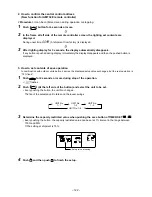
To this model, a switch which can perform the refrigerant recovery (pump down) by the outdoor unit is mounted
so that it is easy to react against the environment at reinstalling or rejection time.
[Operation method]
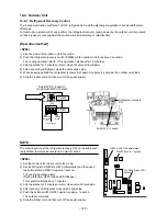
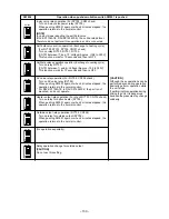
<SP56>
1) See the mode of the indoor unit to fan mode.
2) Push the refrigerant recovery switch (SW802) of the outdoor unit for approx. 2 seconds.
The cooling operation starts. (This operation finishes after 10 minutes.)
3) After operation for 3 minutes or more, close the valve at liquid side.
4) After recovering refrigerant, close the valve at gas side.
5) When keeping pushed the refrigerant recovery SW again for approx. 2 seconds, the outdoor unit stops.
6) Stop the indoor unit and then turn off the power supply.
1234
ON
1234
ON
1234
ON
D800
D801
D802
D803
D804
D805
SW801: Push for 1 second.
W804: All OFF (As initial status)
The D805 (Green LED)
flashes.
NOTE
The electric portion of the refrigerant recovery SW on the sub-board
is electrified, therefore be careful to an electric shock.
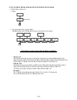
<SP80>
1) Set the mode of the indoor unit to fan mode.
2) Set all DIP switch SW804 to OFF (Initial status) and then push
the button switch SW801 for approx. 1 second.
The cooling operation starts.
(During this time, D805 (Green LED) flashes.)
This operation finishes by 10 minutes.
3) After operation for 3 minutes or more, close valve at liquid side.
4) After recovery of refrigerant, close valve at gas side.
5) Push the button switch SW801 again for approx. 1 second.
The outdoor unit stops.
6) Stop the indoor unit and then turn off the power supply.
N
Power saving
ON
Exchange
to Cooling
only
Existing
piping
Refrigerant recovery
SW
SW802
SW801
Refrigerant recovery
SW
Sub SW P.C. board
Sub SW P.C. board of
model with 3HP or below

