– 66 –
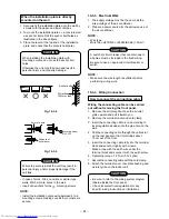
10-4-5. Refrigerant Piping Connection
CAUTION
KEEP IMPORTANT 4 POINTS FOR PIPING
WORK
1. Keep dust and moisture from entering the
pipes.
2. Tight connection (between pipes and unit)
3. Evacuate the air in the connecting pipes
using VACUUM PUMP.
4. Check gas leak. (connected points)
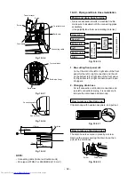
Flaring
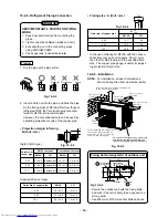
1. Cut the pipe with a pipe cutter.
Fig. 10-4-2
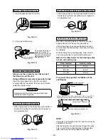
2. Insert a flare nut into the pipe, and flare the pipe.
As the flaring sizes of R410A differ from those of
refrigerant R22, the flare tools newly manufac-
tured for R410A are recommended.
However, the conventional tools can be used by
adjusting projection margin of the copper pipe.
• Projection margin in flaring :
B (Unit : mm)
Rigid (Clutch type)
Fig. 10-4-3
Imperial (Wing nut type)
Outer dia. of
copper pipe
6.35
9.52
12.7
R410A tool used
R410A
R22
0 to 0.5
(Same as left)
0 to 0.5
(Same as left)
0 to 0.5
(Same as left)
Conventional tool used
R410A
R22
1.0 to 1.5
0.5 to 1.0
1.0 to 1.5
0.5 to 1.0
1.0 to 1.5
0.5 to 1.0
Outer dia. of copper pipe
6.35
9.52
12.7
R410A
R22
1.5 to 2.0
1.0 to 1.5
1.5 to 2.0
1.0 to 1.5
2.0 to 2.5
1.5 to 2.0
• Flaring size : A (Unit : mm)
Fig. 10-4-4
Outer dia. of copper pipe
6.35
9.52
12.7
A
R410A
R22
9.1
9.0
13.2
13.0
16.6
16.2
+0
- 0.4
* In the case of flaring for R410A with the conven-
tional flare tool, pull out it approx. 0.5 mm more
than that for R22 to adjust to the specified flare
size. The copper pipe gauge is useful for adjust-
ing projection margin size.
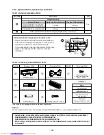
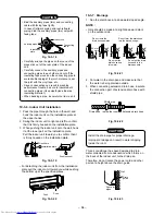
10-4-6. Installation
NOTE : For installation, at least 3 dimensions
should be kept free from obstacles (walls).
Fig. 10-4-5
Fixing bolt arrangement of outdoor unit
Fig. 10-4-6
• Secure the outdoor unit with the fixing bolts
and nuts if the unit is likely to be exposed to a
strong wind.
• Use Ø8 mm or Ø10 mm anchor bolts and nuts.
90˚
Obliquity
Roughness
Warp
B
A
As shown in the figure, hang power cord
and connecting cable downward, and
take out it along piping connection port.
(A)
(B)
(C)
(D)
100 mm or more
from wall
80 mm or more only when unobstructed
to the front and both sides
250 mm or more
from wall
200 mm
or more
50 mm or more
from wall
In principle,
leave open
When installing the outdoor unit,
leave open in at least two of
directions (A), (B), (C) and (D)
shown in the right figure.
310
30
76
30
115 125
600
Suction side
Diffuser
Elongated
drain hole
Drain hole
( 10 )
( 11 )
50
Summary of Contents for RAS-3M18SACV-E
Page 21: ... 21 4 2 Outdoor Unit RAS 3M18SAV E RAS 3M18SACV E ...
Page 110: ... 110 MCC 1438 ...
Page 111: ... 111 MCC 818 ...

