– 71 –
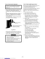
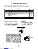
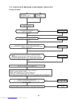
Miswiring (mispiping) check by LED Indication
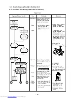
• For this outdoor unit, the self-miswiring (mispiping) check is possible by using five LEDs (1 4 Red).
* LEDs (D800 to D804) locate on the sub-control board underneath of the inverter.
Fig. 10-4-16
LED : Light Emitting Diode
¤
: LED ON
l
: LED OFF
¥
: LED FLASH
LED
During check
Result of
judgement
D800 D801 D802 D803 D804
l
l
l
l
l
¥ ¥ l
l
l
¥ l ¥ l
l
¥ l
l ¥ l
¥
¤
l
l
l
¥ l
¤
l
l
¥ l
l
¤
l
¥
¤
¤
l
l
¥
¤
l
¤
l
¥ l
¤
¤
l
¥
¤
¤
¤
l
Description
Normal operation (no error)
Checking A unit
Checking B unit
Checking C unit
Crush/Clog of Pipe A
Crush/Clog of Pipe B
Crush/Clog of Pipe C
Miswiring/Mispiping or Crush/Clog of Pipe A, B
Miswiring/Mispiping or Crush/Clog of Pipe A, C
Miswiring/Mispiping or Crush/Clog of Pipe B, C
A, B, C Miswiring/Mispiping
Useful Functions
Self-Diagnosis by LED Indication
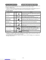
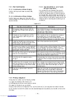
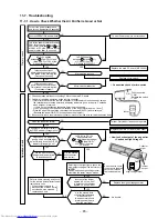
• For this outdoor unit, the self-diagnosis is possible by using five LEDs (1 4 Red).
* LEDs (D800 to D804) are provided on P.C. board of the inverter.
1. If a trouble occurs, LED goes on
according to the contents of
trouble as shown in the left table.
2. When two or more troubles
occur, LEDs go on cyclically
(alternately).
3. Usually, LEDs (Red) go off.
Fig. 10-4-17
IGBT : Insulated Gate Bipolar Transistor
PMV : Pulse Motor Valve
LED : Light Emitting Diode
¤
: LED ON
l
: LED OFF
*1
: Heat pump model only
*1
*1
LED indication
D800 D801 D802 D803 D804
l
l
l
l
l
l
¤
l
l
l
¤
¤
l
l
l
l
l
¤
l
l
¤
l
¤
¤
l
l
l
¤
¤
l
l
¤
¤
l
l
¤
¤
¤
l
l
l
l
l
¤
l
¤
l
¤
l
l
¤
¤
¤
¤
l
¤
l
l
l
¤
¤
¤
l
l
¤
l
¤
¤
l
¤
¤
¤
¤
l
¤
l
l
l
¤
¤
¤
¤
l
¤
¤
¤
l
l
¤
l
l
¤
l
¤
l
¤
¤
l
¤
l
Indoor
alarm code
None
14
16
17
18
18
19
1A
1B
1C
1C
1C
1C
1C
1C
1C
1C
1D
1E
1F
Contents
Normal running
IGBT short circuit, Compressor motor rare short
Trouble on position detecting circuit
Trouble on current detecting circuit
Outdoor heat exchanger temp. sensor (TE) fault
Suction temp. sensor (TS) fault
Discharge temp. sensor (TD) fault
Trouble on outdoor fan motor
Outdoor temp. sensor (TO) fault
Trouble on compressor system
Temp. sensor (TGa) fault at A room gas side
Temp. sensor (TGb) fault at B room gas side
Temp. sensor (TGc) fault at C room gas side
Gas leakage, TS sensor out of place, PMV,
sensor fault
TE sensor out of place, indoor heat exchanger
sensor (TC) out of place, PMV, sensor fault
Miswiring at indoor or outdoor, Gas leakage,
TS, TC sensor out of place, PMV, sensor fault
Communication trouble between MCU
Compressor lock
Trouble on discharge temp, Gas leakage
Compressor break down
Yellow
Red
Miswiring (mis-piping)
check connector (color: Red)
D800D801D802D803D804
LED
Yellow
Red
D800D801D802D803D804
LED
Summary of Contents for RAS-3M18SACV-E
Page 21: ... 21 4 2 Outdoor Unit RAS 3M18SAV E RAS 3M18SACV E ...
Page 110: ... 110 MCC 1438 ...
Page 111: ... 111 MCC 818 ...


