


– 103 –
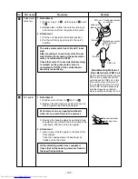
Square
hole
Concave part
Claw
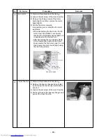
No.
2
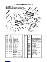
Part name
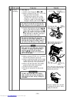
Front cabinet
Procedure
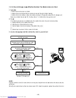
1. Detachment
1) Perform work of item 1 of
1
.
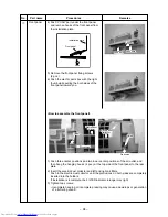
2) Remove the fixing screws (ST1TØ4 × 8L
1 pc.) used to secure the front cabinet and
inverter cover, the screws (ST1TØ4 × 8L
3 pcs.) used to secure the front cabinet at
the bottom, and the fixing screws
(ST1TØ4 × 8L 2 pcs.) used to secure the
motor base.
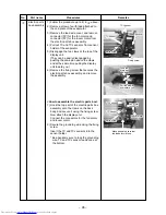
• The front cabinet is fitted into the rear
cabinet (left) at the front left side so pull up
the top of the front cabinet to remove it.
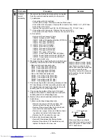
• The left side of the front is made to insert
to the rear cabinet, so remove it pulling
upward.
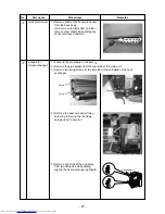
2. Attachment
1) Insert the claw on the front left rear into the
rear cabinet (left).
2) Hook the bottom part of the front right side
onto the concave section of the bottom
plate. Insert the claw of the rear cabinet
(right) into the square hole in the front
cabinet.
3) Return the screws that were removed above
to their original positions, and attach
them.the main unit, and attach it pushing
upward.
Remarks
Summary of Contents for RAS-3M18SACV-E
Page 21: ... 21 4 2 Outdoor Unit RAS 3M18SAV E RAS 3M18SACV E ...
Page 110: ... 110 MCC 1438 ...
Page 111: ... 111 MCC 818 ...