


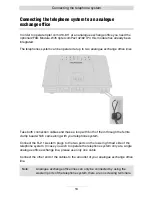
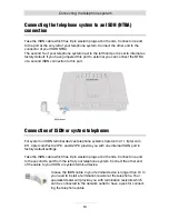


Connecting the telephone system
24
2
1
3
4
4
Changing S
0
port settings
As factory default setting the first (left hand side) S
0
port of the telephone system is
set to external for operating at the NTBA of an ISDN connection, the second S
0
port
(second jack from the left) is set to internal intern for operating ISDN or system tele-
phones.
I you wish to operate the telephone system at two ISDN connections you can also set
the second S
0
port to external.
In case the telephone system shall not be operated at an ISDN connection you can
also set the first S
0
port to internal for connecting additional ISDN or system tele-
phones.
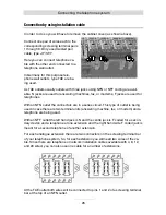
In order to do so please remove the cabinet cover as shown above.
To set the first (standard: external) S
0
bus to internal move the jumper from
JP504 and 502 (designation TE) to
JP503 and JP501 in front of them
(designation NT) (2).
To set the second (standard: internal)
S
0
bus to external move the jumper
from JP509 and 507 (designation NT)
to JP510 and JP508 right behind
them (designation TE) (3).
As an alternative to connecting NTBA
or ISDN and system telephones to the
S
0
ports of the telephone system you
can also use installation cable at the
screwing terminals KL501 and 502
(4). The pinning is printed on the
printed circuit board.
If you wish to go into two directions
with your wiring from an S
0
port which
is set to internal you will have to re-
move the internal termination resis-
tors. In order to do so please remove the two jumpers of JP505 (1) for the first S
0
port
(left hand side) and the two jumpers of JP506 (1) for the second S
0
port (second port
from the left).