
74
74
NC20 - Manual - 01 - 2015
FUNCTION CHARACTERISTICS
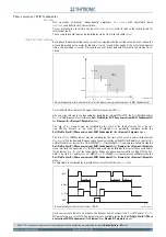
Fun_49_AL1.ai
Common configuration
&
dD
θ
/dt + D
θ
/T = (Ith/I
B
)
2
/T
Init DTheta
D
θ
≥
DthAL1
DthAL1
Binary input INx
T
0
Logic
INx
t
ON
INx
t
ON
INx
t
OFF
T
0
n.o.
n.c.
INx
t
OFF
I
t h
≥
1
K
INR
DthAL1
CB-State
ON
≡
Enable element
(Pickup within CLP)
(Pickup outside CLP)
Pickup - CLP setting change
Block1, Block2
T
0
t
DthCLP
DthCLPMode
t
D t h C L P
I
t h
∙
K
I N R
TRIP
P
ING
M
A
TRIX
(LED
+R
EL
A
Y
S
)
A
B
C
A =“1”
A =“0 or OFF”
Output
t
DthCLP
DthAL1 Enable
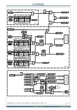
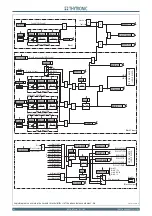
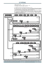
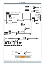
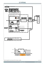
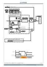
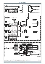
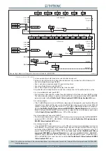
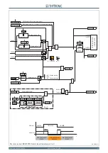
DThhAL1 thermal image (49) block diagram
t
DthCLP
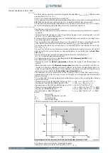
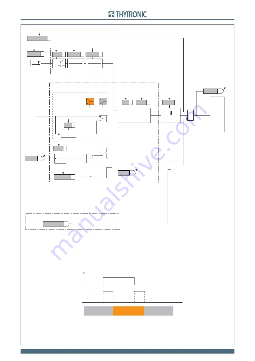
CB State
CB OPEN
CB CLOSED
CB OPEN
Output t
DthCLP
t
0.1 s
HIGH THRESHOLD/
BLOCK
LOW THRESHOLD/
UNBLOCK
HIGH THRESHOLD/
BLOCK
A = ON - Change setting
B = OFF
C = ON - Element blocking
DthAL1-L
DthAL1-K
≥
1
CLP Dth
T
DthIN
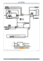
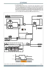
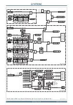
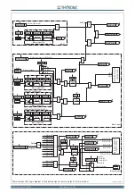
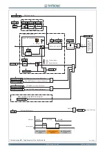
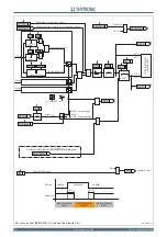
Thermal image (49) - Logic diagram of the first alarm threshold