
213
NC20 - Manual - 01 - 2015
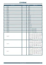
APPENDIX
213
NC20 - Manual - 01 - 2015
APPENDIX
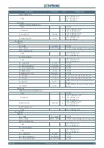
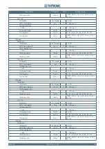
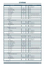
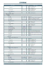
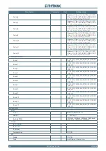
Description
Parameter Unit
Setting range
Common confi guration
Initial thermal image
DthIN
DThe-
taB
0.0 ... 1.0 step = 0.1
Reduction factor at inrush
KINR
1.0 ... 3.0 step = 0.1
Thermal time constant
T
min
1 ... 200 step = 1
DthCLP Operating mode
DthCLP Mode
OFF | ON - Element blocking | ON - Change setting
DthCLP Activation time
Value
s
0.00 ... 9.99 step = 0.01
10.0 ... 100.0 step = 0.1
DthAL1 Element
DthAL1 Enable
DthAL1 Enable
OFF | ON
49 First alarm threshold
DthAL1
DThe-
taB
0.3 ... 1.0 step = 0.1
DthAL1 Logical block
DthAL1BLK1
OFF | ON
DthAL1 Input selective block
DthAL1BLK2IN
OFF | ON
DthAL1 Output selective block
DthAL1BLK2OUT
OFF | ON
DthAL1 Alarm relays
DthAL1-K
K1 | K2 | K3 | K4 | K5 | K6 | K7 | K8 | K9 | K10
DthAL1 Alarm LEDs
DthAL1-L
START | TRIP | L1 | L2 | L3 | L4 | L5 | L6 | L7 | L8 |
L9 | L10
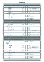
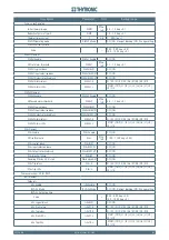
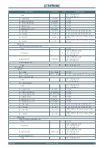
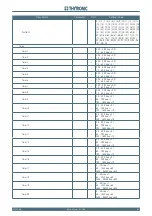
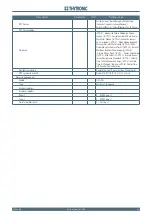
DthAL2 Element
DthAL2 Enable
DthAL2 Enable
OFF | ON
49 Second alarm threshold
DthAL2
DThe-
taB
0.5 ... 1.2 step = 0.1
DthAL2 Logical block
DthAL2BLK1
OFF | ON
DthAL2 Input selective block
DthAL2BLK2IN
OFF | ON
DthAL2 Output selective block
DthAL2BLK2OUT
OFF | ON
DthAL2 Alarm relays
DthAL2-K
K1 | K2 | K3 | K4 | K5 | K6 | K7 | K8 | K9 | K10
DthAL2 Alarm LEDs
DthAL2-L
START | TRIP | L1 | L2 | L3 | L4 | L5 | L6 | L7 | L8 |
L9 | L10
Dth> Element
Dth> Enable
Dth> Enable
OFF | ON
49 Trip threshold
Dth>
DThe-
taB
1.100 ... 1.300 step = 0.001
Dth> Logical block
Dth>BLK1
OFF | ON
Dth> Input selective block
Dth>BLK2IN
OFF | ON
Dth> Output selective block
Dth>BLK2OUT
OFF | ON
Dth> Breaker failure
Dth>BF
OFF | ON
Disabling Dth> by 50-51 start
Dth>disby50-51
OFF | ON
Dth> Trip relays
Dth>-K
K1 | K2 | K3 | K4 | K5 | K6 | K7 | K8 | K9 | K10
Dth> Trip LEDs
Dth>-L
START | TRIP | L1 | L2 | L3 | L4 | L5 | L6 | L7 | L8 |
L9 | L10
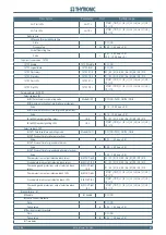
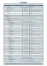
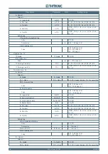
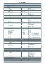
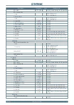
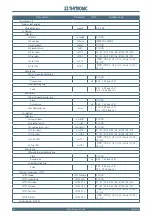
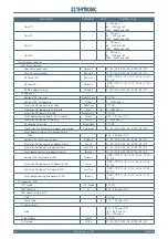
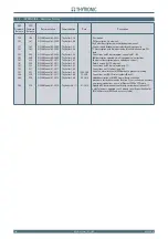
Phase overcurrent - 50/51 RMS
I>AL Element
Setpoints
I>AL Enable
I>AL Enable
OFF | ON
ICLP>AL Mode
ICLP>AL Mode
OFF | ON - Element blocking | ON - Change setting
ICLP>AL Activation time
Value
s
0.00 ... 9.99 step = 0.01
10.0 ... 100.0 step = 0.1
I>AL Logical block
I>ALBLK1
OFF | ON
I>AL Start relays
I>ALST-K
K1 | K2 | K3 | K4 | K5 | K6 | K7 | K8 | K9 | K10
I>AL Trip relays
I>ALTR-K
K1 | K2 | K3 | K4 | K5 | K6 | K7 | K8 | K9 | K10
I>AL Start LEDs
I>ALST-L
START | TRIP | L1 | L2 | L3 | L4 | L5 | L6 | L7 | L8 |
L9 | L10
I>AL Trip LEDs
I>ALTR-L
START | TRIP | L1 | L2 | L3 | L4 | L5 | L6 | L7 | L8 |
L9 | L10