


23
NC20 - Manual - 01 - 2015
TECHNICAL DATA
3.8
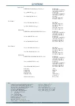
CONTROL AND MONITORING
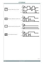
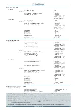
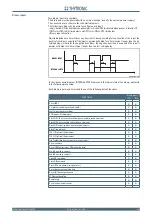
Trip Circuit Supervision - 74TCS
Operate time:
One binary input supervision
40 s
Two binary inputs supervision
2 s
Reset time delay:
One binary input supervision
6 s
Two binary inputs supervision
0.6 s
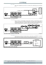
Selective block - BLOCK2
Selective block IN:
BLIN1 Selective block operating mode (
ModeBLIN1
)
OFF-ON IPh/IE-ON IPh-ON IE
BLIN maximum activation time for phase protections (
t
B-IPh)
0.10...10.00 s (step 0.01 s)
BLIN maximum activation time for ground protections (
t
B-IE )
0.10...10.00 s (step 0.01 s)
Selective block OUT:
BLOUT1 Selective block operating mode (
ModeBLOUT1
)
OFF-ON IPh/IE-ON IPh-ON IE
BLOUT Dropout time for phase protections (
t
F -IPh
)
0.00...1.00 s (step 0.01 s)
BLOUT Dropout time for ground protections (
t
F -IE
)
0.00...1.00 s (step 0.01 s)
BLOUT Dropout time for ground and phase protections (
t
F-IPh/IE
) 0.00...10.00 s (step 0.01 s)
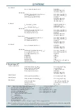
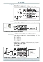
Circuit Breaker supervision
Circuit breaker diagnostic
Number of CB trips threshold (
N.Open
)
0...10000
(step 1)
Cumulative CB tripping currents threshold (
SumI
) 0....5000
I
n
(step 1
I
n
)
Cumulative CB tripping I
2
t threshold (
SumI^2t
)
0....5000
I
n
2
∙s
(step 1
I
n
2
∙s)
Circuit Breaker opening time for I^2t calculation (
t
break
)
0.05...1.00 s (step 0.01 s)
Circuit Breaker maximum allowed opening time (
t
break
>)
0.05...1.00 s (step 0.01 s)
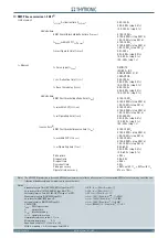
CT supervision - 74CT
74CT Threshold (
S<)
0.10...0.95
(step 0.01)
74CT Overcurrent threshold (
I
*
)
0.10...1.00
I
n
(step 0.01
I
n
)
S<
Operating time delay (
t
S
<)
0.03...200
s
0.03...9.99 s (step 0.01 s)
10.0...99.9 s (step 0.1 s)
100...200 s (step 1 s)
Dropout ratio for the
I
*
pickup
0.95...0.98
Dropout time
≤
0.05 s
Pickup accuracy
S<
± 1% with 0.1
I
n
, ± 0.5% with 1
I
n
Pickup accuracy
I
*
± 0.5% with 0.1
I
n
, ± 0.2% with 1
I
n
Operate
time
accuracy
5%
or
±
10 ms
Pilot wire diagnostic
BLOUT1 Diagnostic pulse period (
PulseBLOUT1)
OFF-0.1-1-5-10-60-120
s
BLIN1 Diagnostic pulse control time interval (
PulseBLIN1)
OFF-0.1-1-5-10-60-120
s
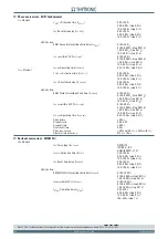
Demand measures
Fix on demand period (
t
F I X )
1...60 min (step 1 min)
Rolling on demand period (
t
ROL )
1...60 min (step 1 min)
Number of cycles for rolling on demand (
N.
ROL )
1...24 (step 1)
Oscillography (DFR)
[1]
Format
COMTRADE
Recording mode
circular
Sampling rate
>
1
kHz
Trigger setup:
Pre-trigger time
0.05...1.00 s (step 0.01 s)
Post-trigger time
0.05...60.00 s (step 0.05 s)
Set sample channels
i
L1
,
u
L1
,
i
L2
,
u
L2
,
i
L3
,
u
L3
,
i
N
Set analog channels
Analog 1...Analog 12
Frequency,
I
L1
,
I
L2
,
I
L3
,
I
EC
,
I
N
,
I
NC
,
I
L1rms
,
I
L2rms
,
I
L3rms
,
U
L1
,
U
L2
,
U
L3
,
φ
N
(
Phi
N
),
φ
NC
(
Phi
NC
), T1...T8
[2]
Set digital channels:
Digital 1...Digital 12
K1... K6, K7...K10,
IN1, IN2, IN3...IN42
[3]
Note 1 For the DFR function a licence is required; call Thytronic for purchasing.
Note 2 The measures of temperature are available only when the MPT module on Thybus is enabled (eigth Pt100 inputs)
Note 3 Output relay K7...K10 and binary input IN3...IN42 states are available only when the concerning I/O circuits are implemented (MRI and MID16
modules on Thybus)
•
•
•
•
•
•
•
•
•
•
•
•
•
•
•
•
•
•
•
•