


16
16
NC20 - Manual - 01 - 2015
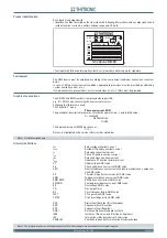
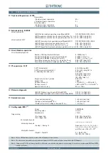
TECHNICAL DATA
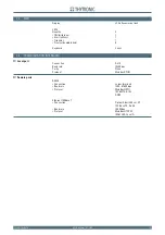
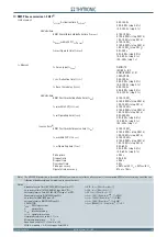
3.6
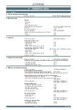
GENERAL SETTINGS
Relay nominal frequency (
f
n
)
50, 60 Hz
Relay phase nominal current (
I
n
)
1 A or 5 A
[1]
Phase CT primary nominal current (
I
np
)
1
A...10
kA
1...499 A (step 1 A)
500...4990 A (step 10 A)
5000...10000 A (step 100 A)
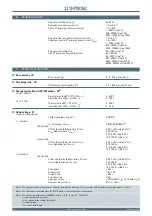
Relay unbalance neutral nominal current (
I
Nn
)
1 A o 5 A
[1]
Unbalance neutral CT primary nominal current (
I
Nnp
)
1 A...10 kA
1...499 A (step 1 A)
500...4990 A (step 10 A)
5000...10000 A (step 100 A)
Relay nominal voltage (
U
n
)
50...130 V (step 1 V)
Line VT primary nominal voltage (
U
np
)
50
V...500
kV
50...499 V (step 1 V)
500...4990 V (step 10 V)
5000...49900 V (step 100 V)
50000...500000 V (step 1000 V)
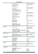
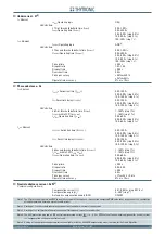
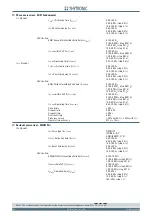
3.7
PROTECTIVE FUNCTIONS
Base current - IB
Base current (
I
B
) 0.10...2.50
I
n
(step 0.01
I
n
)
Discharge time - TD
tD Discharge operating time (
t
D
)
0.1...100.0 min (step 0.1 min)
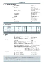
Thermal protection with Pt100 probes - 26
[2]
ThAL1...8 Alarm:
Alarm threshold 26 PT1...PT8 (
Th
AL1...8
)
0...200
°C
Operating time ThAL1...8 (t
Th
AL1...8
)
0....100
s
Th>1...8 Trip:
Trip threshold 26 PT1...PT8 (
Th>
1...8
)
0...200
°C
Operating time ThAL1...8 (t
Th>
1...8
)
0....100
s
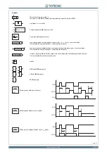
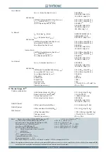
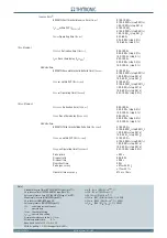
Undervoltage - 27
Common confi guration:
27 Operating logic (
Logic
27)
AND/OR
U< Element
U
< Curve type (
U
<
Curve
)
DEFINITE/INVERSE
[3]
Defi nite time
27 First threshold defi nite time (
U<
def
)
0.05...1.10
U
n
(step 0.01
U
n
)
U<
def
Operating time (
t
U
<
def
)
0.03...100.0
s
0.03...9.99 s (step 0.01 s)
10.0...100.0 s (step 0.1 s)
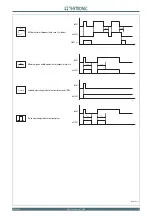
Inverse time
27 First threshold inverse time (
U<
inv
)
0.05...1.10
U
n
(step 0.01
U
n
)
U<
inv
Operating time (
t
U
<
inv
)
0.10...100.0
s
0.10...9.99 s (step 0.01 s)
10.0...100.0 s (step 0.1 s)
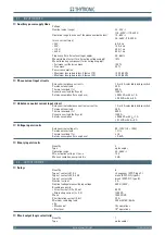
U<<Element
Defi nite time
27 Second threshold defi nite time (
U<<
def
) 0.05...1.10
U
n
(step 0.01
U
n
)
U<<
def
Operating time (
t
U
<<
def
)
0.03...100.0 s
0.03...9.99 s (step 0.01 s)
10.0...100.0 s (step 0.1 s)
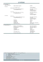
Pickup time
≤
0.03 s
Dropout
ratio
1.03...1.05
Dropout time
≤
0.05 s
Overshoot
time
0.03
s
Pickup accuracy
±
0.3% with 0.1
U
n
/
E
n
, ±
0.1% with 1
U
n
/
E
n
Operate time accuracy
5% or ±
10 ms
Note 1 The nominal current settings doesn’t concern the protection elements; they must agree with hardware setting (dip-switch 1 A or 5 A) .
Note 2 The 26 element is available when the MPT module is connect on Thybus and enabled
Note 3 The mathematical formula for INVERSE curve is: t=
0.75
∙
t
U
<
inv
/ [1 - (
U
/
U
<
inv
)]
t = operating time (in seconds)
t
U
<
inv
= operatie time setting (in seconds)
U = input voltage
U<
inv
= threshold setting