


56
56
NC20 - Manual - 01 - 2015
FUNCTION CHARACTERISTICS
TD Discharge time
Preface
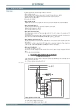
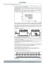
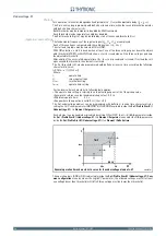
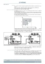
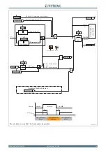
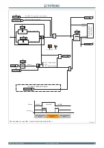
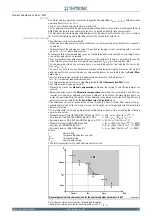
The discharge timer may be enabled or disabled.
When enabled it is started by the second threshold (I<<) of the undercurrent protection (even if that
trip is not programmed to any output relay or LED).
One or more output relay and/or LED can be allocated; they are automatically preset with No-latched
operating mode.
The reconnection inhibit output signal will be active until the set time has elapsed and is used to
inhibit the reconnection of a charged capacitor bank to a live network and limit the inrush current.
A signalling LED can be set to fl ag the bank capacitor discharge in progress.
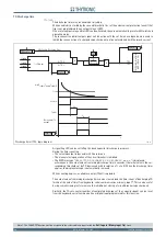
During the timer counting:
The selected output relays and/or LEDs are driven
The manual closing operation of the circuit breaker is inhibited.
The MMI message “
CAPACITOR DISCHARGE IN PROGRESS xxx s
” is displayed,
where xxxx is the actual value of remaining discharge time in seconds, (the initial value is the cor-
responding threshold set by TD decreased with resolution of 1 s to 0). When the discharge timer
expires, the display message is automatically removed.
When counting expires, a suitable counter (TDcnt) is updated.
The actual value of remaining discharge time can be cleared (and the timer count of discharging TD
forced at the end of time) from keyboard, serial communication or binary input
[1]
. This can be useful
during commissioning tests to remove the inhibition at closing of circuit breaker capacitor bank.
Similarly, the TDcnt counter (number of complete discharges of the capacitor bank) can be reset
from the keyboard, serial communication or digital input programmed for this function.
Note 1 The
reset tD
function must be assigned to the selected binary input inside the
Set \ Inputs \ Binary input 1(x)
menu.
•
•
•
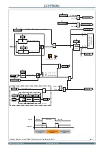
TD.ai
I
L 1RMS
I
L 2RMS
I
L 3RMS
t
D
0
T
Trip TD
Trip TD
ON
≡
Enable Discharge timer
&
&
TR
IP
P
ING
M
A
TR
IX
(LED
+R
EL
A
Y
S
)
TD Enable
t
<<
Trip
I<
<
Delay timer
T
D
output
Start
I<
<
min[
I
L 1RMS,
I
L 2RMS
I
L 2RMS
]
t
t
D
TD-K
TD-L
t
D
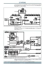
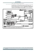
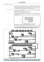
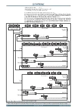
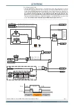
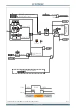
Discharge timer (TD) - logic diagram
Trip I<<
I<<TR-K
I<< Element
I<<TR-L
I<
<
def