110
110
NC20 - Manual - 01 - 2015
FUNCTION CHARACTERISTICS
Breaker failure - BF
Preface
When the protection issues a trip command but, because an anomaly, the circuit breaker cannot
open, the breaker failure protection issues a back-up trip command to trip adjacent circuit breakers.
The breaker failure function may be started by internal protective function (if associated with BF) or
by external protections.
Operation and settings
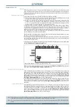
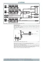
The starting of the timer occurs if both the following conditions are fi lled:
Start and trip of internal protective elements (trip of elements matched with BF protection) or, trip
of external protections acquired by means binary input, if enabled;
The CB is closed (the CB state may be acquired by means two binary inputs connected to the
auxiliary contacts 52a and 52b) or the fundamental component of at least one phase current
I
L1
,
I
L2
,
I
L3
is greater than the
I
BF>
adjustable threshold or the fundamental component of the
residual current
I
E
is greater than the
I
EBF>
adjustable threshold.
The breaker failure protection reliability is improved by means of the CB position control or phase
or residuaI current measure; the trip can arise also for wrong auxiliary contacts state (if the current
is greater than the adjustable threshold ) or for trip of external protections (frequency, voltage,..)
without current (with CB closed information supplied from state of auxiliary contacts).
If the information concerning the CB position is not achievable (for instance the auxiliary contacts
are unavailable), such control must be disabled.
If both conditions are held along the set operate time
t
BF
, the BF element trips at deadline, vice versa
the timer is cleared and the function is restored.
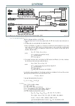
To the purpose to restore the BF element as quickly as possible, with start of the same protection
(see A condition), additionally to the trip of some internal protections, their starts are required (start
reset is faster than trip reset).
The element may be enabled or disabled by setting
ON
the
BF Enable
parameter available inside
the
Set \ Profi le A(or B) \ Breaker failure-BF
menu.
All the
I
BF>
,
I
EBF
and
t
BF
parameters can be set separately for
Profi le A
and
Profi le B
; they are avail-
able inside the
Set \ Profi le A(or B) \ Breaker failure-BF
menu.
BF start from Circuit breaker
If the
CB Input
parameter (BF Start from circuit breaker) is set to
ON
, and two binary inputs are
designed for acquire the 52a and 52b auxiliary contacts
[1]
, the control of the CB position is enabled. If
the information concerning the CB position is not available, such control must be disabled by setting
OFF
the
CB Input
parameter. The parameter is available inside the
Set \ Profi le A(or B) \ Breaker
failure-BF
menu, the
52a
and
52b
function must be assigned to the selected binary inputs inside
Set \ Inputs \ Binary input IN1(x)
menus (IN1 or INx matching).
To enable the breaker failure protection to operate with trips coming from external protections, one
binary input must be designed to acquire the relative contacts. The
TripProtExt
function must be
assigned to the selected binary input inside the
Set \ Inputs \ Binary input IN1(2...)
menus (IN1 or IN...
matching).
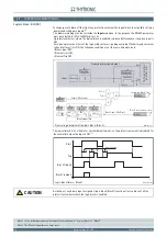
Logical block (Block1)
If the
BF-BLK1
parameter (BF logical block) is set to
ON
, and a binary input is designed for logical
block (Block1), the breaker failure protection is blocked off whenever the given input is active. The
trip timer is held in reset condition, so the operate time counting starts when the input block goes
down.
[2]
The enabling parameter is available inside the
Set \ Profi le A(or B) \ Breaker failure-BF
menu, while the
Block1
function must be assigned to the selected binary input inside the
Set \
Inputs \ Binary input IN1(x)
menus (IN1 or INx matching).
Note 1 Both auxiliary contact state 52a and 52b must be acquired (two binary inputs are required) with Fw version previous to 1.60; with later versions,
giving up an inconsistency occurs, one logical input for the acquisition of a contact (52nd or 52b ) may suffi ce
Note 2 The exhaustive treatment of the logic block (Block 1) function may be found in the “Logic Block” paragraph inside
CONTROL AND MONITORING
section
A)
B)
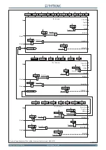
all-FBF.ai
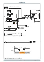
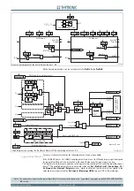
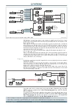
General logic diagram of the breaker failure element - BF
Block 1
B L K1 B F
I
L1
. . .
I
L3
I
EC
5 2 a / 5 2 b
Tr ip P r o t E x t
S t ar t B F
Tr ip B F
Block1
&
BF-BLK1
BF Enable
CB Input
I
BF
>
I
EBF
>
t
BF

