24
7 Liner Replacement
3/8" (9.5 mm) BLUE LINER FOR SPRAYING 1/8" (3.2 mm) WIRE
7/16" (11.1 mm) ORANGE LINER FOR SPRAYING 3/16" (4.8 mm) WIRE
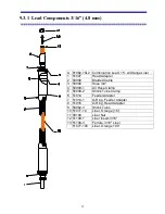
Refer to drawing in (SECTION 9.3) Disconnect leads (51062) liner assembly from wire
feeder. Lay the liner assembly out flat and straight. Then remove liner nut (50109),
insert (51019-1) and ferrule (51109-3), this will expose the liner and allow it to be
removed by pulling the liner out of the liner assembly.
Replace the new liner by first rounding the edge of the tubing with a file, then making
sure the assembly is straight, push the liner through the assembly until it reaches the spray
head adapter (51007). Verify the position by looking down the end of the spray head
adapter - the liner should be visible about an inch and a quarter (32 mm) from the end.
IMPORTANT
- The liner must be seated in this manner to allow smooth wire flow and
an air seal.
Install ferrule and liner nut, then push liner into cable assembly, eliminating any slack, cut
off liner about 1 ¼” (32 mm) from end of feeder adapter fitting and replace liner insert
and tighten the liner nut.
Summary of Contents for BRIDGEMASTER
Page 20: ...7 3 System Assembly drawing shows optional straighteners...
Page 30: ...17 6 2 1 Angle Spray Nozzle 3 16 4 8 mm Wire Head...
Page 31: ...18 6 3 Air Nozzle Alignment 1 8 3 2 mm Wire Head...
Page 32: ...19 6 3 2 Angle Spray Nozzle 1 8 3 2 mm Wire Head...
Page 57: ...44 9 4 1 System Wiring...

