background image


17 

6.2.1 Angle Spray Nozzle 3/16” (4.8 mm) Wire Head 


Summary of Contents for BRIDGEMASTER

Page 1: ...12513 4624410 5791560 6683271 B2 OWNER S MANUAL OPERATIONS AND MAINTENANCE MANUFACTURED BY SILVERDALE WASHINGTON USA Phone 360 692 6469 Toll Free 877 884 6428 Fax 360 447 8314 Web Site www thermioninc...

Page 2: ...procedures It covers applicable documents relating to thermal spray equipment consumables and safety It also contains operator qualification and coating analysis forms Note This standard is being inco...

Page 3: ...epair of ferrous and non ferrous substrates Included are requirements for the qualification of thermal spray procedures and operators requirements and guidance for use of thermal spray material and eq...

Page 4: ...es and in process quality control QC checkpoints are specified ANSI AWS C2 18B XX SSPC CS 23 00B XX NACE TPC XB Specification for the Application of Thermal Spray Coatings Metallizing of Aluminum Zinc...

Page 5: ...te No comparable ISO standard Inactive This guide presents the recommend practices for the metallographic techniques and procedures for characterizing thermal spray coatings Cutting mounting grinding...

Page 6: ...requirements of thermally sprayed structures Part 3 Standard quality requirements ISO DIS 14922 4 Thermal spraying Quality requirements of thermally sprayed structures Part 4 Elementary quality requir...

Page 7: ...Spraying and fusing of thermally sprayed coatings of self fluxing alloys Edition 1 monolingual ICS 25 220 20 Descriptors coating processes coatings melting specifications spraying thermal spraying Las...

Page 8: ...trical code standards appropriate for your requirements A certified electrician should always hook primary leads to the electrical grid source with the appropriate safety disconnects WARNING ARC RAYS...

Page 9: ...e feed unit for a period of 90 ninety days from date of purchase B Express Warranty Any express warranty not provided herein and any implied warranty guarantee or representation as to performance and...

Page 10: ...ntact your distributor For the safe and successful use of this equipment be sure the information contained in this manual reaches the operator Extra copies of this manual are available upon request Pl...

Page 11: ...nd consulting with your distributor you have additional questions regarding the operation of this piece of equipment please call fax or write Thermion PO Box 780 Silverdale WA 98383 USA Voice 360 692...

Page 12: ...rds 2 3 Threshold Limits for Air Concentration of Hazardous Material 2 4 Personal Protection 2 5 Eye Protection 2 6 Environment 7 3 System Assembly Diagram 3 1 Location 3 2 Power Supply 3 3 Component...

Page 13: ...ours 6 5 4 Monthly Maintenance 160 hours 24 7 Liner Replacement 7 1 Installation Replacing Small Wire Liners 26 8 Parts Required for Various Wire Sizes 27 9 Components Section 9 1 Cable Components 9 2...

Page 14: ...ORTANT which identify different levels of hazards DANGER indicates an operational procedure which if not followed will cause SEVERE injury to the operator service personnel or bystanders WARNING state...

Page 15: ...to the spray gun from the feeder These three assemblies make up the Front End Assembly 1 3 3 Arc Shorting Control Arc spray systems typically have an inherent problem of arc shorting This condition o...

Page 16: ...tion Manual located in Sections 6 4 6 5 4 DANGER All dust having considerable caloric value can be explosive This dust includes flour starch hard rubber dust wood flour aluminum dust and the dust of o...

Page 17: ...as to the effectiveness of the ventilating and exhaust system or as to the presence of airborne particles which the operator might inhale consult a competent industrial hygienist Because any finely d...

Page 18: ...tool Use clean dry compressed air only 2 4 Personal Protection WARNING The electric arc generated at the front of the gun is very bright and emits ultraviolet light rays The eyes and skin must be gua...

Page 19: ...5 Eye Protection Standard Welding Shields and Lens CAUTION the hardened green Shade 9 lens is within the shade range recommended for arc spraying However the choice of lens shade may be based on visu...

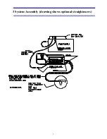
Page 20: ...7 3 System Assembly drawing shows optional straighteners...

Page 21: ...Feeder Hook Up To Power Supply Wire Feeder hook up to the power supply is performed by connecting the control lead and two welding cables 3 3 2 Front End Assembly Hook up WARNING Electric shock can ki...

Page 22: ...lume Optimum regulated air pressure for general purpose spraying should be 95 PSI Lower air pressures can be used to obtain special high profile rough coatings i e non skid applications Equipment come...

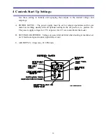
Page 23: ...et for remote operations and for gas metal arc welding usually with all optional setting in the off position i e pulsars etc The power supply voltage for CV or power for CC are controlled at the feede...

Page 24: ...witch allows running the wire feed motor feeding wire through the liner to the head without energizing air or the power supply 4 4 Fusing The wire feed system is dual fused An external fuse or breaker...

Page 25: ...unback The wire runback feature creates a gap at the wire s end to aid arc starting When the spraying is stopped the wires are retracted on the end of the stopping sequence A potentiometer adjustment...

Page 26: ...itional spools of metalizing wire It has been learned in practice that lubricating is not necessary when operating with 3 16 zinc or 85 15 zinc aluminum wire 2 Round off the free end of the metalizing...

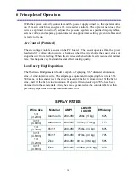
Page 27: ...normal rate This happens very fast and does not effect coating quality Low Energy High Deposition The Thermion Bridgemaster Model is capable of spraying 3 16 diameter aluminum zinc or zinc aluminum w...

Page 28: ...hout fear of dealloying However this equipment runs 3 32 2 4 mm material best at 200 250 amps and 1 8 3 2 mm and 3 16 4 8 mm between 250 and 500 amps Alloyed material of 1 16 1 6 mm and 3 32 2 4 mm si...

Page 29: ...3 16 4 8 mm Wire Head Align contact tips to maintain wires directly in center of air nozzle Set contact tips prior to operation perform spraying for a few minutes then check wire position and realign...

Page 30: ...17 6 2 1 Angle Spray Nozzle 3 16 4 8 mm Wire Head...

Page 31: ...18 6 3 Air Nozzle Alignment 1 8 3 2 mm Wire Head...

Page 32: ...19 6 3 2 Angle Spray Nozzle 1 8 3 2 mm Wire Head...

Page 33: ...e liner system and it will accumulate behind the contact tip in the contact tube This can cause enough friction to impair wire feed Remove the contact tube from the head then remove the tip from the c...

Page 34: ...ubricate the o rings and socket with a light grease prior to insertion The grease is necessary for a good air seal at both the feeder end and at the head 6 4 3 Feeder Unit The feeder unit being low ma...

Page 35: ...an be soaked with lubricant at the dispenser will lubricate the wire and reduce friction in the delivery tube 6 SHIELD Clean shield as needed during operations CAUTION MAY BE HOT 7 HEAD Clean head as...

Page 36: ...the side covers then remove the dust from inside the machine with an air hose 6 5 4 Monthly Maintenance 160 Hours CAUTION Perform all electrical work with power secured 1 TIPS Replace 2 CONTACT TUBE H...

Page 37: ...e the new liner by first rounding the edge of the tubing with a file then making sure the assembly is straight push the liner through the assembly until it reaches the spray head adapter 51007 Verify...

Page 38: ...le and liner nut then push liner into cable assembly eliminating any slack cut off liner about 1 1 2 37 mm from end of feeder adapter fitting and replace liner insert and tighten the liner nut Verify...

Page 39: ...065 2 mm 2 each 50019 50018 2 each 50081 2 mm 8each 50076 2 each 50109 2 each 51109 2 2 each 50018 A 2 each 3 32 11 gauge 2 4 mm SMALL WIRE 50064 50065 3 32 2 each 50019 50018 2 each 50081 3 32 8 each...

Page 40: ...ly 9 3 1 Lead Components 3 16 4 8 mm 9 3 1 1 Lead Components 1 8 3 2 mm Wire 9 3 1 2 Lead Components 3 32 2 3 mm Smaller Wire 9 3 2 Spray Head Components 3 16 4 8 mm Wire 9 3 2 1 Spray Head Components...

Page 41: ...28 9 1 Cable Components A 50058 Power Supply Cord B 51060 XX Control Lead Assy 1 51057 Control Cable Connector 2 51059 19 Pin Female Connector C 50045 13 Trigger Cord...

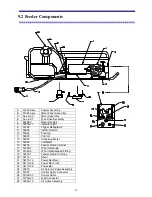
Page 42: ...50022 Pot Amp 11 50025 Pot Volt 12 50023 Amperage Meter 13 50024 Volt Meter 16 54036 Feeder Frame Cabinet 17 51078 1 Wire Inlet Guide 18 51045 2 Wire Inlet Bulkhead Fitting 19 50033 1 Feeder Frame Air...

Page 43: ...GUIDE INSERT 05N58 7 ROLL PIN 3 16 X 1 3 4 62350066 22 CLAMPING PLATE 2075495 8 WIRE DRIVE GUIDE CLAMP 50108 23 CENTER WIRE GUIDE 50031 11 9 4 FLAT WASHER 2075524 24 CLAPPER ASSY 2075500 10 17 SCREW...

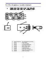
Page 44: ...Straightener Assembly 1 54201 Roller Mount 2 54202 V Groove Rollers 3 54203 Cam Adjuster Bushing 4 54204 Roller Mount Screw 5 54205 Bearing Plate Mount 6 54206 Insulator Support 7 54207 Support Mount...

Page 45: ...54046 1 Retaining Ring 2 54031 01 Gear Insulated 3 50047 Gear Stop Washer 4 54035 Assembly Motor Assembly 5 54035 KEY Motor Key 6 92356A58 Carriage Bolts 7 54035 3 Motor Mount NS 54035 1 Coupling Slee...

Page 46: ...embly Optional A 54300 Industrial Cart Assembly 1 54301 Frame 2 54302 Tool Box 3 54303 Front Swivel Caster 4 54303 1 Caster Swivel Brake 5 54304 Rear Rigid Caster 6 54305 Dual Welding Lead Clamp 7 543...

Page 47: ...34 9 3 Front End Assembly A 54000 1 Front End Assembly 1 See Sec 9 3 1 Lead Components 2 See Sec 9 3 2 Head Components 3 See Sec 9 3 3 Trigger Assembly 4 54045 Trigger Cord...

Page 48: ...ded Cable 3 50009 Hose 3 4 4 50009 1 Air Hose Clamp 5 50009 2 Shrink Tube Clamp 6 51014 Feeder Adapter 7 51014 1 O Ring Feeder Adapter 8 51016 O Ring Head Adapter 9 50062 3 Shrink Tube 10 51077 16 Lin...

Page 49: ...Head Adapter 2 50008 Braided Cable 3 50009 Hose 3 4 4 50009 1 Air Hose Clamp 5 50009 2 Shrink Tube Clamp 6 51014 Feeder Adapter 7 51014 1 O Ring Feeder Adapt 8 51016 O Ring Head Adapt 9 50062 3 Shrin...

Page 50: ...Comb Lead Braided Cable 2 50009 Hose 3 4 3 50009 1 Air Hose Clamp 4 50009 2 Shrink Tube Clamp 5 51014 Feeder Adapter 6 51014 1 O Ring Feeder Adapt 7 51016 O Ring Head Adapt 8 50018 14 Liner Violet 9...

Page 51: ...50080 Clamp Shield 3 50005 Clamp Contact Tube 4 51064S 1 Nozzle Fan Side Air Jet 5 51076 Contact Tube 6 51065 3 16 Contact Tip 7 51079 Shield 8 50066 Center Air Nozzle Tip 9 50066 1 Center Air Nozzle...

Page 52: ...y 3 50064B 1 Side Air Jet Nozzle 4 50065 XX Tip Contact 5 50066 Center Air Nozzle Tip 6 50066 1 Center Air Nozzle Tube 7 50066 2 Center Air Nozzle O Ring 8 50076 Contact Tube 1 8 50079 Shield 9 50080...

Page 53: ...Angle Spray Head Components 3 16 4 8 mm 1 50005 Head Contact Tube Clamp 2 51064 Head Angle Spray 3 51085 Head Angle Spray Nozzle 4 51065 XX Head Tip Contact 5 51076 Head Contact Tube 6 50080 Head Shi...

Page 54: ...ly 1 50005 Head Contact Tube Clamp 2 50064B Head 125 3 2 mm Fan Spray 3 50085 Head Angle Spray Nozzle 4 50065 XX Head Tip Contact 5 50076 Head Contact Tube 6 50080 Head Shield Clamp CAUTION CENTER AIR...

Page 55: ...igger Assembly A 50045 Assy Handle Assembly W Out Cord 1 50003 20 Cap Screws 2 50015 Strain Relief 3 50012 1 Air Switch 4 50012 2 Air Switch Boot 5 50011 Trigger Switch 6 50012 Handle 50045 13 Handle...

Page 56: ...ssembly 1 50072 2 24 Pin Wire Connector 2 51082 Back Up Timer 3 51072G PC Board 4 51059 1 Connector 19 Pin 5 50058 Power Supply Cord 6 50051 Bridge Rectifier 7 50052 Transformer 8 50049 Relay 9 51048...

Page 57: ...44 9 4 1 System Wiring...

Page 58: ...ective Part Spraying begins then stops after a few minutes 1 Low Voltage 2 Dirty Liners 1 Set Voltage to 29 or higher 2 Lubricate and Clean Liners Spray pattern is rough uneven or odd shape 1 Low Air...

Page 59: ...3 Raise Voltage 4 Clean Replace Tubes Tips Excessive dust and smoke 1 High Voltage 2 Lower Voltage Slit spray pattern 1 Low Voltage 2 Air Nozzles Out of Alignment 1 Raise Voltage 2 Adjust Air Nozzles...

Reviews: