11
4 Controls
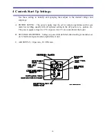
Full control of all functions can be provided at the wire feeder. One multi-conductor lead
provides the inter-connection from the power supply to the control box and from the
control box to the feeder.
4.1 Voltage
Voltage is controllable at the wire feeder. Voltage is an indicator of arc gap; the higher
the voltage, the larger the distance between the two wires in the arc.
4.2 Amperage
An amp meter is provided at the feeder for operator convenience. The amperage is
controlled through the wire feed speed control, which is located on the wire feed unit.
4.3 Wire Inch
An inching switch allows running the wire feed motor, feeding wire through the liner to
the head without energizing air or the power supply.
4.4 Fusing
The wire feed system is dual-fused. An external fuse or breaker in the power supply
protects the total system; while internal fuses that are located on the motor controller add
additional protection to the controller. An indicator light is provided to show operators
that 110 VAC power is available at the feed unit.
4.5 Handle & Trigger Assembly
The Trigger is located in the Handle Assembly. This switch energizes the power supply
contactor, turns on atomization air, and starts wire feed.
IMPORTANT
The power leads must be connected to the wire feeder to start wire feed
when using the Trigger. The inch switch will feed wire without the power lead
connection.
Summary of Contents for BRIDGEMASTER
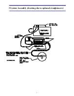
Page 20: ...7 3 System Assembly drawing shows optional straighteners...
Page 30: ...17 6 2 1 Angle Spray Nozzle 3 16 4 8 mm Wire Head...
Page 31: ...18 6 3 Air Nozzle Alignment 1 8 3 2 mm Wire Head...
Page 32: ...19 6 3 2 Angle Spray Nozzle 1 8 3 2 mm Wire Head...
Page 57: ...44 9 4 1 System Wiring...

