41
6-7. Usage of Remote Sensing Function (PW18-1.3ATS, PW26-1ATS & PW8-5ADPS only)
6-7-1.
Remote sensing terminals
When a load is connected with the output terminals, the voltage at the terminals of the load is
subject to load fluctuation due to voltage drop, which is caused by the contact resistance of the
output terminals or resistance of the connected wires. This load fluctuation is proportional to the
current. The PW18-1.3ATS and PW26-1ATS, PW8-5ADPS have the remote sensing function of
channels carrying 5 A or more. The remote sensing function allows the user to set the voltage at
the terminals of the load finely.
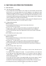
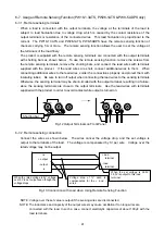
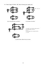
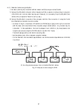
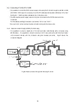
The product is supplied with the remote sensing terminals are connected with the output terminals
with shorting bars as shown below. To use the remote sensing function, remove the screws from
the remote sensing terminals, remove the shorting bars, and connect the lead wires with terminals
supplied with the product. If the lead wires are short, connect additional wires to them. When
connecting additional wires to the lead wires, solder the connections properly and protect them with
insulating tubes. Be sure to turn off output when connecting the lead wires to the sensing terminals.
Otherwise, the sensing terminal may be short-circuited with the output terminal, resulting in a failure,
since the sensing terminals are close to the output terminals. Use the lead wires with terminals
supplied with the product in order to avoid contact while output is turned on.
6-7-2.
Remote sensing connection
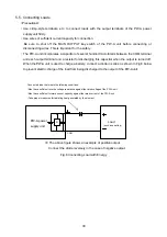
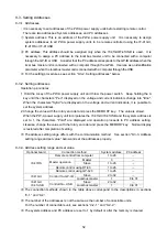
Connect the wires as shown below. The wires cancel the voltage drop, and the set voltage is
output to the terminals of the load. The voltage is compensated by 1V per wire. Voltage over the
rated voltage may not be output.
Fig.13 Connection with Load when Using Remote Sensing Function
NOTE: Voltage over the set value is output if the sensing wires are disconnected.
NOTE: The inductance and capacity of the output wires may cause oscillation if too long wires are
connected with the load. In such a case, connect electrolytic capacitors of about 100µF with the
load terminals.
+load
terminal
When the set voltage is 3.00V,
3.00V is output to this load
terminal.
Voltage drop of 1V each is
compensated for the + and -
wires.
When the rated voltage is 6V, voltage
over 6V is not output even though the
voltage drops.
-load
terminal
+s
-s
+ output
- output
Fig.12 Output Terminals on Front Panel
0
6V
(5A) COM
2
0 6V
(5A) COM
2
-S
+S
-S
+S
Shorting bar

