28
SLAS826F – MARCH 2015 – REVISED MARCH 2017
Product Folder Links:
Specifications
Copyright © 2015–2017, Texas Instruments Incorporated
(1)
Stresses beyond those listed under
Absolute Maximum Ratings
may cause permanent damage to the device. These are stress ratings
only, and functional operation of the device at these or any other conditions beyond those indicated under
Recommended Operating
Conditions
is not implied. Exposure to absolute-maximum-rated conditions for extended periods may affect device reliability.
(2)
Voltage differences between DVCC and AVCC exceeding the specified limits may cause malfunction of the device.
(3)
All voltages referenced to V
SS
.
(4)
Higher temperature may be applied during board soldering according to the current JEDEC J-STD-020 specification with peak reflow
temperatures not higher than classified on the device label on the shipping boxes or reels.
5
Specifications
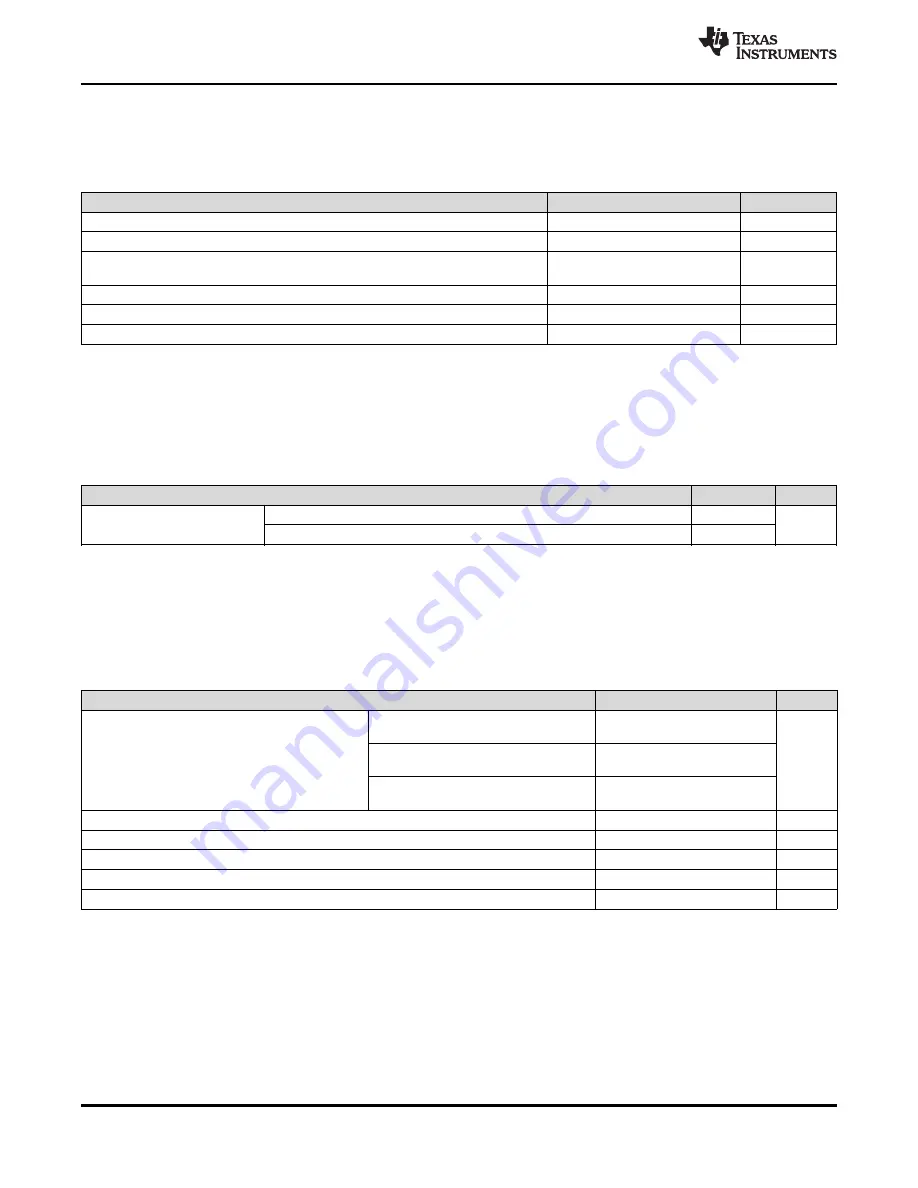
5.1
Absolute Maximum Ratings
(1)
over recommended ranges of supply voltage and operating free-air temperature (unless otherwise noted)
MIN
MAX
UNIT
Voltage applied at DVCC and AVCC pins to V
SS
–0.3
4.17
V
Voltage difference between DVCC and AVCC pins
(2)
±0.3
V
Voltage applied to any pin
(3)
–0.3
V
CC
+ 0.3 V
(4.17 V MAX)
V
Diode current at any device pin
±2
mA
Storage temperature, T
stg
(4)
–40
125
°C
Maximum junction temperature, T
J
95
°C
(1)
JEDEC document JEP155 states that 500-V HBM allows safe manufacturing with a standard ESD control process. Pins listed as
±1000 V may actually have higher performance.
(2)
All pins except DVSS3 pass HBM up to ±1000 V. The DVSS3 pin is used for TI internal test purposes. Connect the DVSS3 pin to supply
ground on the customer application board.
(3)
JEDEC document JEP157 states that 250-V CDM allows safe manufacturing with a standard ESD control process. Pins listed as ±250 V
may actually have higher performance.
5.2
ESD Ratings
VALUE
UNIT
V
(ESD)
Electrostatic discharge
Human-body model (HBM), per ANSI/ESDA/JEDEC JS-001
(1) (2)
±1000
V
Charged-device model (CDM), per JEDEC specification JESD22-C101
(3)
±250
(1)
TI recommends powering AV
CC
and DV
CC
from the same source. A maximum difference of ±0.1 V between AV
CC
and DV
CC
can be
tolerated during power up and operation. See
for decoupling capacitor recommendations.
(2)
Supply voltage must not change faster than 1 V/ms. Faster changes can cause the VCCDET to trigger a reset even within the
recommended supply voltage range.
(3)
Modules may have a different supply voltage range specification. See the specification of the respective module in this data sheet.
(4)
Does not include I/O currents (driven by application requirements).
(5)
Operating frequency may require the flash to be accessed with wait states. See
for further details.
5.3
Recommended Operating Conditions
Typical data are based on V
CC
= 3.0 V, T
A
= 25°C (unless otherwise noted)
MIN
NOM
MAX
UNIT
V
CC
Supply voltage range at all DVCC and
AVCC pins
(1) (2) (3)
At power-up (with internal V
CC
supervision)
1.71
3.7
V
Normal operation with internal V
CC
supervision
1.71
3.7
Normal operation without internal V
CC
supervision
1.62
3.7
V
SS
Supply voltage on all DVSS and AVSS pins
0
V
I
INRUSH
Inrush current into the V
CC
pins
(4)
100
mA
f
MCLK
Frequency of the CPU and AHB clock in the system
(5)
0
48
MHz
T
A
Operating free-air temperature
–40
85
°C
T
J
Operating junction temperature
–40
85
°C


