background image

Document 57.4400.7200 - 1

st 

Edition 03/2005

INDEX

6

17

TELELIFT 3713 Elite - 4017 - 4514

SCHEMES

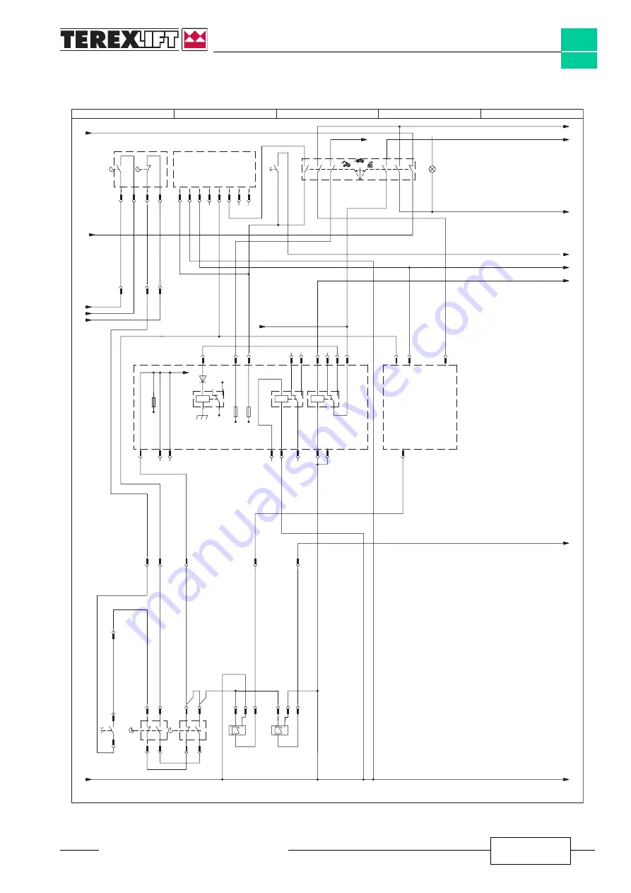
6.4.7

Sheet 7 of 9

TECNORD

CONTROL UNIT

+15

S31

2

0

1

BOOM LIFTING

RIGHT SENSOR

PLA

T.SCALE CHANGE

OUTRIGGER DOWN

OVERLOAD SIGNAL

GROUND

POWER SUPPL

Y

+15

+30

+30

LIMIT SWITCH

RIGHT

OUTRIGGER

LIMIT SWITCH

LEFT

OUTRIGGER

BOOM LIFTING

LEFT SENSOR

S52

S51

OVERLOAD WARNING SYSTEM

3B6

+30

SWITCH GEAR

NOT ENGAGED

N1

N1

N1

A-N1

R-N1

A-N1

70

H-R1.5

Z-N1.5

C1

R-N1

B-G1

B-N1

G-M1

XJ1

A7

XJ1

B4

XJ1

C7

XJ1

A3

H/N1

9.1

A/R1

A-G1

H-R1.5

1.2

G-M1

9.1

V1.5

8.1

X6

2

F13

10A

H-R1.5

9.1

C-R1

2.5

G-M1

2.5

H/N1

H/N1

A/N1

8.1

M-N1

B-G1

9.1

H9

S35

S34 S33 S32

S30

A-N1

9.1

X21

6

X53

B

X53

A

X53

C

B41

C-B1

X7

10

X7

3

X7

11

X7

4

X7

2

K18

86

87a

87

85

30

S6b

S6a

N1

X7

13

X7

11

X7

12

X7

6

X7

7

X7

5

K19

86

87a

87

85

30

K22

86

87a

87

85

30

X4

6

X5

6

F25

10A

X21

1

X5

4

S10

B-N1

R-N1

B-G1

B-G1

A-G1

B-G1

A/R1

A/R1

A-R1

C-N1

C/N1

S-G1

B-G1

L-G1

N1

B-N1

9.1

X53

C

X53

A

X53

B

X22

6

X5

3

X22

10

X22

7

X26

3

S-G1

3.5

X26

4

N1

6.5

L-G1

1.5

3

B38

X52

3

X52

4

X52

1

X52

2

X51

3

X51

4

X51

1

X51

2

X25

7

X25

4

X25

5

X25

6

X25

8

X25

2

X25

3

X25

1

2

4

1

X26

2

31

8.1

31

6.5

X5

9

53

9.2

F18

10A

3

1

2

4

5

X22a

B54

RELAY

CARD

WORK

SELECTOR

Courtesy of Crane.Market 

Summary of Contents for TELELIFT 3713 Elite

Page 1: ...P MANUAL Code 57 4400 7200 1st Edition 03 2005 Handler with telescopic boom TELELIFT 3713 Elite from serial n 11376 to serial n 14856 TELELIFT 4017 up to serial n 14866 TELELIFT 4514 up to serial n 15...

Page 2: ...Document 57 4400 7200 1st Edition 03 2005 INDEX TELELIFT 3713 Elite 4017 4514 2 Intentionally blank page Courtesy of Crane Market...

Page 3: ...e same in any way to unauthorised workshops and third parties in general and not to photocopy or reproduce this manual or parts of the same in any way without the prior written authorisation of TEREXL...

Page 4: ...Courtesy of Crane Market...

Page 5: ...nual in their workshop without disclosing the information in the same in any way to unauthorised workshops and third parties in general and not to photocopy or reproduce this manual or parts of the sa...

Page 6: ...NDEX Revision Revised Issued No date pages Notes by 1 03 2005 Publication 2 3 4 5 6 7 8 9 10 11 12 13 14 15 16 17 18 19 20 21 22 23 24 25 26 27 28 29 30 31 32 33 34 35 36 TELELIFT 3713 Elite 4017 4514...

Page 7: ...TION Sect 1 SAFETY RULES Sect 2 TECHNICAL SPECIFICATIONS Sect 3 SCHEDULED MAINTENANCE INSPECTIONS Sect 4 SCHEDULED MAINTENANCE PROCEDURES Sect 5 TROUBLESHOOTING Sect 6 SCHEMES Sect 7 REPAIR PROCEDURES...

Page 8: ...ation Literature valid up to serial number TELELIFT 3713 Elite from serial n 11376 to serial n 14856 TELELIFT 4017 up to serial n 14866 TELELIFT 4514 up to serial n 15124 INDEX TELELIFT 3713 Elite 401...

Page 9: ...st procedures However several procedures require specialized skills as well as specific tools and equipment Intheseinstances westronglyrecommendlettingservice and repair the machine at an authorized T...

Page 10: ...de The assembly of the two pumps involves they have a rotation velocity equal to the speed of the diesel engine A third Casappa open loop gear pump with fixed displacement pos 4 with a displacement of...

Page 11: ...ll be available for the functions of the telescopic boom The steering circuit is protected against input overpressures by a pressure reducing valve set at 140 bar On the two delivery lines there are o...

Page 12: ...n relation to the command signal they receive from such joystick via the control unit Module 1 of the distributor controls the telescopic boom lifting cylinder pos 17 This cylinder has one single acti...

Page 13: ...ase and safety function The control module of this element of the distributor is the ON OFF electrical type with integrated electronics On the feeding lines of this cylinder there are two quick fit co...

Page 14: ...he discharge line parking brake locked The two pressure switches set at 10 20 bar send an electrical warning signal when the parking brake is activated brake locked The Bucher electro hydraulic modula...

Page 15: ...it of the machine The flows of pumps pos 3 and pos 4 are conveyed in the latter The oil cooled down by the heat exchanger is sent back to the tank pos 10 When the machine is equipped with man platform...

Page 16: ...150 bar 30 bar X1 G M Ev1 Ev2 Ev3 Ev4 Ev5 Ev6 Ev14 Ev15 Ev7 Ev8 Ev9 Ev10 Ev11 Ev12 Pv1 Pv2 Pv3 Pv4 24 26 25 27 22 23 15 13 14 12 35 20 19 29 30 31 32 28 21 37 18 37 37 17 11 1 4 2 16 10 5 33 34 7 36 6...

Page 17: ...TY INFORMATION SECTION INDEX 1 1 Safety rules page 2 1 1 1 Personal safety 2 1 1 2 Workplace safety 2 1 2 General remarks 4 1 3 Servicemen s requisites 4 1 3 1 Personal protective equipment 5 1 4 Gene...

Page 18: ...lve your own as well as the others safety and that can result in serious or lethal injury Draws the attention to situations that involve your own as well as the others safety and that can result in se...

Page 19: ...could get into machine components and cause damage Be sure that your workshop or work area is properly ventilated and well lit Besureanyforklift overheadcraneorother lifting or supporting device is f...

Page 20: ...doubt ContactTEREXLIFT theassistanceserviceisatyour disposal Addresses phone and fax numbers are giveninthecoverandinthetitle pageofthismanual 1 3 SERVICEMEN S REQUISITES The operators who use the ma...

Page 21: ...ments and represent a danger for personnel 1 4 2 PRECAUTIONS DURING WORK Do not walk or stop under raised loads or machine parts supported by hydraulic cylinders or ropes only Keep the machine handhol...

Page 22: ...o check for pressure leaks Fine jets of air oil or fuel can injure you Neither smoke nor use open flames if there is a risk of fire or close to fuel oil or batteries Do not leave fuel cans or bottles...

Page 23: ...chine sound levels 4 2 11 Vibration levels 5 2 12 Refuelling 5 2 13 Tightening torques 6 2 14 Drill diameters for threads 8 2 15 Standard tightening torques for fitting seals 9 2 16 Locking material 1...

Page 24: ...G Length to the front tyres mm 3910 3910 3910 3910 ft H Length to the attachment holding plate mm 5610 5610 5610 6290 ft I Ground clearance mm 460 460 460 460 ft J Max width with extended outriggers m...

Page 25: ...8 8 8 8 Travel speed km h 37 37 37 35 Max slope with full load 54 54 54 50 either forward or reverse motion 2 6 PAYLOAD AND REACH TELELIFT 3713Elite 3713T Elite 4017 4514 Max lifting height with outri...

Page 26: ...ers in line 4 cylinders in line 4 cylinders in line 4 strokes 4 strokes 4 strokes 4 strokes direct injection direct injection direct injection direct injection Bore x Stroke mm 103 x 127 105 x 127 105...

Page 27: ...bance In such cases the operator is required to take suitable measures 2 12 REFUELLING TELELIFT 3713Elite 3713T Elite 4017 4514 Diesel engine l 11 5 11 5 11 5 11 5 Engine cooling system l 15 15 15 15...

Page 28: ...293 8 264 4 353 0 317 7 1 5 24 14 10 8 218 3 196 5 308 1 277 3 369 3 332 4 18 2 5 27 14 12 8 288 7 259 8 406 1 365 5 487 7 436 9 1 5 27 14 12 8 314 2 282 8 442 8 398 5 530 6 477 5 20 2 5 30 17 12 10...

Page 29: ...5 0 275 0 120 0 170 0 1 5 210 0 295 0 130 0 185 0 18 2 5 270 0 390 0 170 0 245 0 1 5 305 0 425 0 190 0 265 0 20 2 5 305 0 540 0 190 0 340 0 1 5 425 0 600 0 260 0 375 0 22 2 5 510 0 720 0 320 0 450 0 1...

Page 30: ...12 x 1 75 10 44 10 10 10 20 x 1 5 10 68 10 38 10 50 M 14 x 2 12 21 11 83 12 00 x 1 5 12 68 12 38 12 50 M 16 x 2 14 21 13 84 14 00 x 1 5 14 68 14 38 14 50 M 18 x 2 5 15 74 15 29 15 50 x 1 5 16 68 16 38...

Page 31: ...6 12 190 1 5 8 12 225 1 7 8 12 270 2 12 245 2 1 4 12 360 FRONT O LOK Parker SEALS Thread TIGHTENING diameter TORQUES 0 10 FRONT O LOK Parker SEALS inc mm Nm 9 16 18 25 11 16 16 40 13 16 16 55 1 14 80...

Page 32: ...8 M20x1 5 L 42 245 G 1 4 M12x1 5 S 6 50 G 1 4 M14x1 5 S 8 50 G 3 8 M16x1 5 S 10 80 G 3 8 M18x1 5 S 12 80 G 1 2 M22x1 5 S 16 105 G 3 4 M27x2 S 20 220 G 1 M33x2 S 25 370 G 1 1 4 M42x2 S 30 500 G 1 1 2 M...

Page 33: ...Loctite 573 Formed in place gasket 150 0 2 Slow Excellent Loctite 574 Formed in place gasket 150 0 5 Rapid Excellent Loctite 510 Formed in place gasket 200 0 2 Moderate Excellent Loctite 5699 Formed i...

Page 34: ...STRANDED ROPES Use ropes or other hoisting accessories suitable to the weight of the part to be handled For ropes refer to the following table STRANDED ROPES Rope diameter Max admissible load mm kg 10...

Page 35: ...protection equipment e g goggles gloves facial screen etc Wrap up the end of the pipe to be disconnected with some rags and slowly loosen the pipe connector so that air comes out as slow as possible...

Page 36: ...er 1 06 0401 0219 Pump and drive motor O ring 2 53 3001 0900 Exhaust manifold 1 632696 Solenoid valves solenoid 1 07 0738 0000 Cardan joint spider 1 05 4329 0000 Accumulator for boom lowering line cyl...

Page 37: ...1 07 0700 0000 Hydromatik oil filter cartridge 1 09 4604 0000 Tank internal filter 1 Aspirated engine 639399 Internal engine air filter cartridge 1 639400 External engine air filter cartridge 2 638243...

Page 38: ...ntrol block solenoid 1 56 0012 0009 Outriggers limit switch 1 640536 Seals kit fork pitching cylinder 1 637650 Fuse 3A 2 07 0709 0419 Steering cylinder kit 1 07 0703 0193 Fuse 5A 2 634972 Fuse 7 5 A 2...

Page 39: ...529 0092 Seals kit lifting cylinder 1 07 0741 0016 Seals kit main control block 1 05 4329 0000 Boom lowering line cylinder accumulator 1 05 4329 0001 Pressure switch 1 639395 Seals kit attachment lock...

Page 40: ...17 4514 TECHNICAL SPECIFICATIONS 2 20 MACHINE PAINT COLOUR STANDARD machines GREY RAL 7012 WHITE RAL 1013 MAT BLACK RAL 9005 from June 2004 for cylinders AUSA machines ORANGE RAL 2004 GENIE machines B...

Page 41: ...M EXTENSION RETRACTION BOOM LIFTING LOWERING Telelift 3713 Elite Time s up down Max engine speed 16 8 Min engine speed 33 20 Telelift 4017 Time s up down Max engine speed 16 13 Min engine speed 41 29...

Page 42: ...OVEMENT Telelift 3713 Elite Time s up down Max engine speed 5 5 Min engine speed 11 14 Telelift 4017 Time s up down Max engine speed 6 7 Min engine speed 13 16 MACHINE SWAY Telelift 3713 Elite Time s...

Page 43: ...ylinder B annexes 1 proceed as follows By means of valve A set the distributor pressure to 300 bar while moving one of the cylinders to stroke end With the engine running at maximum speed tilt the for...

Page 44: ...D E F 4 1 CALIBRATION OF THE DA CURVE Do this operation with extreme caution The proper functioning of pump and transmission depends on this calibration Set the forward neutral reverse selector to th...

Page 45: ...nometer to position T annexes 4 Depress the foot brake some times until the manometer starts increasing When it stops the value shown is the calibration value of valve R which must be 140 bar If the d...

Page 46: ...ne to max speed and make sure that the pressure reaches 220 bar with the stabilizer to end of stroke If the pressure value isn t correct act on valve L of the distributor 8 CHECKING THE ADJUSTMENT SCR...

Page 47: ...Document 57 4400 7200 1st Edition 03 2005 INDEX 2 25 TELELIFT 3713 Elite 4017 4514 TECHNICAL SPECIFICATIONS HYDRAULIC SYSTEM LIFTING annex 1 A B Courtesy of Crane Market...

Page 48: ...Document 57 4400 7200 1st Edition 03 2005 INDEX 2 26 TELELIFT 3713 Elite 4017 4514 TECHNICAL SPECIFICATIONS HYDRAULIC SYSTEM FORK BALANCE annex 2 S Courtesy of Crane Market...

Page 49: ...400 7200 1st Edition 03 2005 INDEX 2 27 TELELIFT 3713 Elite 4017 4514 TECHNICAL SPECIFICATIONS HYDRAULIC SYSTEM TRANSMISSION annex 3 D C E G 0 60 30 200 10 50 40 0 600 300 200 100 500 400 Courtesy of...

Page 50: ...t 57 4400 7200 1st Edition 03 2005 INDEX 2 28 TELELIFT 3713 Elite 4017 4514 TECHNICAL SPECIFICATIONS R T 0 300 150 100 50 250 200 annex 4 HYDRAULIC SYSTEM SERVICE AND PARKING BRAKES Courtesy of Crane...

Page 51: ...cument 57 4400 7200 1st Edition 03 2005 INDEX 2 29 TELELIFT 3713 Elite 4017 4514 TECHNICAL SPECIFICATIONS annex 5 HYDRAULIC SYSTEM POWER STEERING X Z A 0 300 150 100 50 250 200 Courtesy of Crane Marke...

Page 52: ...Document 57 4400 7200 1st Edition 03 2005 INDEX 2 30 TELELIFT 3713 Elite 4017 4514 TECHNICAL SPECIFICATIONS HYDRAULIC SYSTEM STABILIZERS annex 6 L V Courtesy of Crane Market...

Page 53: ...e and the relevant meaning are shown below Press to enter number 0 Press to enter number 1 Press to confirm the sequence entered The access code currently used is 1001 Therefore you should enter the f...

Page 54: ...t 7 50 m referred to the front part of the wheels Press to confirm the LOADED calibration of the machine and check that the alarm triggers Hold the load on the forks raise the outriggers and extend th...

Page 55: ...turned on a flashing 0 should appear on the display if the auto confirmation via software is not programmed and you should confirm pressing Once the machine has been calibrated proceed with some test...

Page 56: ...he operation data of the TECNORD control unit proceed as follows Go to the driving place and remove the cover located at the left bottom with respect to the steering wheel Prepare the electrical cable...

Page 57: ...05 INDEX 2 35 TELELIFT 3713 Elite 4017 4514 TECHNICAL SPECIFICATIONS Connect the other end of the cable to the special socket on the PC Proceed with the checks and settings using the control and manag...

Page 58: ...outrigger Activation button for the down movement of the right outrigger Left sway activation button Right sway activation button Dead man on the platform buttons panel It reads the following alarm an...

Page 59: ...ode 1 Such conditions would activate the manoeuvres associated to the button without control if the signal were not OFF when the Jobsite or Platform mode is selected Therefore until the control unit d...

Page 60: ...4 2 and 4 1V 84 2 with rest position at 2 5V 0 REMARK PERC_cmd Vcontrol 2 5 1 9 Corsa MASSIMA FW e BW mean the maximum stroke in one direction and the maximum stroke in the opposite drection With the...

Page 61: ...che fork forward back pitching Once you ve chosen the movement you can set in the MIN and MAX boxes the value in percentage of the movement speed you desire MIN means the minimum speed you can have fo...

Page 62: ...graduated bars show you the movements of the boom and forks in real time according to their effective speed The joystick control button and the 4th function button become ON and OFF depending if they...

Page 63: ...8 Pin 16 Pin 23 10 X2 RED PINK YELLOW GREEN WHITE BROWN COLOUR R9 2 6 7 8 4 5 3 VB VB X2 1 1 VB BASKET NC OUTRIGGERS CUTOFF SPARE OUTRIGGERS BASKET SIGNAL VB VB VB X3B WHITE VB BROWN VB 2 1 19 PINK IN...

Page 64: ...D4 ON if the interlock relay is active machine safe without alarms D Software version existing in the DLE unit this function allows you to see the software version included in the DLE unit according t...

Page 65: ...ions if the load limiter cutout key is used when the instrument is started Action The relay or the cable can be shorted check The limiter s outputs do not deactivate Switch off and on the machine and...

Page 66: ...7200 1st Edition 03 2005 INDEX 2 44 TELELIFT 3713 Elite 4017 4514 TECHNICAL SPECIFICATIONS DLE MONITORING WITH 3B6 WINSCOPE PARAMETERS Simulation of the parameters Simulation of the variables Courtesy...

Page 67: ...tils menu select Prj Selection Type in the correct path of file CFG IT or look for the same in the Windows folders suing the Browse function The file must not necessarily be in the path shown in the f...

Page 68: ...s that is DLE_01 current Hardware Type RS232 Port COM1 usually this is the port but it can change in relation to the connected PC Baudrate 19200 DLE_00 Hardware Type RS232 Port COM1 usually this is th...

Page 69: ...want to download a setting of the machine onto a PC or Carica Load if you want to transfer a setting saved in the PC into the machine The following window will be displayed so you can type in the pass...

Page 70: ...e parameters and variables no password is needed All you have to do is connecting the DLE display with the power cord supplied by TEREXLIFT code 07 0736 0014 and proceed as explained below Connect the...

Page 71: ...4514 TECHNICAL SPECIFICATIONS If you want to check the system parameters and variables you have to open the relevant windows and check the values contained in these Open the parameters windows as show...

Page 72: ...ables window as shown in picture 8 Clicking with the mouse another window opens see picture 9 which will display the real variations on the machine so you can compare the same with the parameters If d...

Page 73: ...n When the platform is selected the limiter uses this default 110 load increase of 10 instead of the SpanForche datum current value 125 13 DeltaSpanGomme Limiter intervention percentage in case of wor...

Page 74: ...Document 57 4400 7200 1st Edition 03 2005 INDEX 2 52 TELELIFT 3713 Elite 4017 4514 TECHNICAL SPECIFICATIONS Intentionally blank page Courtesy of Crane Market...

Page 75: ...LELIFT 3713 Elite 4017 4514 SCHEDULED MAINTENANCE INSPECTIONS Section 3 SCHEDULED MAINTENANCE INSPECTIONS SECTION INDEX 3 1 Introduction page 2 3 2 About this section 3 3 3 Maintenance table 4 3 4 Mai...

Page 76: ...ed on the maintenance of this machine Scheduled maintenance must be carried out at the intervals indicated in the MAINTENANCE REPORT Failuretoproperlycompleteeachinspectionwhen required may cause deat...

Page 77: ...Monthly A B C Six month A B C D Yearly A B C D E Two years A B C D E F Maintenance table The maintenance table contains general information on the type of intervention to be carried out at a certain i...

Page 78: ...n filter A 9 Check the engine coolant level A 10 Check and clean the radiator A 11 Check the hydraulic oil level in the tank A 12 Check the greasing of the boom section pads A 13 Grease the attachment...

Page 79: ...y C 2 Change the engine oil and relevant filter C 3 Check the oil level in the front and rear differential gears C 4 Check the oil level in the four wheel reduction gears C 5 Check the main filtering...

Page 80: ...fixing screws D 4 Check the backlash between pins and bushings in all joints D 5 Change the hydraulic oil filter of the transmission D 6 Change the hydraulic oil filter in the tank D 7 Have the hydra...

Page 81: ...4400 7200 1st Edition 03 2005 INDEX 3 7 TELELIFT 3713 Elite 4017 4514 SCHEDULED MAINTENANCE INSPECTIONS TABLE F Every 2000 working hours or every two years F 1 Change the engine coolant Courtesy of C...

Page 82: ...A 16 Lighting electric system A 17 Efficiency of braking system and parking brake A 18 Steering selection system A 19 Fork balancing system A 20 Safety devices Table B Y N R Within the first 50 workin...

Page 83: ...NCE PROCEDURES Section 4 SCHEDULED MAINTENANCE PROCEDURES SECTION INDEX 4 1 Introduction page 2 4 2 About this section 3 4 3 TABLE A procedures 3 4 4 TABLE B procedures 23 4 5 TABLE C procedures 29 4...

Page 84: ...the MAINTENANCE REPORT Failuretoproperlycompleteeachinspectionwhen required may cause death serious injury or substantial machine damage Immediately tag and remove from service a damaged or malfuncti...

Page 85: ...ur own as well as the others safety and that can result in serious or lethal injury Draws the attention either to situations that involve your own as well as the others safety and that can result in m...

Page 86: ...tal axis Clean the plug all around then remove it and check if oil is level with the hole If necessary add new oil through hole A until it is level Refit the plug Place a container of suitable size un...

Page 87: ...ise the outrigger and lower the machine to the ground Re tighten all nuts to a torque 440 Nm Check the tightening of wheels one hour after the job They might get loose until they do not stay correct O...

Page 88: ...Before starting your daily work proceed with a random check of the bolts For the correct tightening torques please refer to par 2 13 in section 2 Technical Specifications A 4 CHECK THE COUPLINGS FOR O...

Page 89: ...use Contact Terexlift Service Centre if replacement manuals are needed A 6 INSPECT THE DECALS AND PLACARDS Maintaining all of safety and instructional decals and placardsingoodconditionismandatoryfor...

Page 90: ...emovetheouterelementD Clean the filter bowl Dry clean the cartridge max pressure 6 bar and direct the air jet from inside to outside Checkforcracksinthefilteringelementbyintroducing a lamp inside Smea...

Page 91: ...fe distance Weekly check the coolant level within pan A before starting working when coolant is cold When necessary add clean water or an antifreeze mixture through cap B Change the antifreeze mixture...

Page 92: ...Cleaning using compressed air Direct a jet of compressed air toward radiator paying attention not to damage its fins Remove any loose particles of dirt with some water Cleaning using water under press...

Page 93: ...ilunderpressurecanpenetrate the skin Do not use your fingers but a piece of cardboard to detect oil leaks Check the hydraulic oil level visually through the special level A fitted into the tank When n...

Page 94: ...four sides of the profile These pads are secured to both fixed and mobile part of every section At regular intervals check that the telescopes are well greased in correspondence of the sliding pads I...

Page 95: ...ughly cleanthe intervention zone to avoid that mud dust or other matters can mix with the lubricant and reduce or annihilate the lubrication effect Remove any old grease with a degreaser from the tele...

Page 96: ...tters can mix with the lubricant and reduce or annihilate the lubrication effect Remove any old grease with a degreaser from the telescopes before smearing them with new grease Regularly grease the ma...

Page 97: ...d 10 start flashing the buzzer sounds an error code is shown on the display and the machine enters the alarm mode and cannot be operated The meaning of the error messages is shown in Section 2 To do a...

Page 98: ...replaced use the table below as a reference A B C When switched on lamps get hot Before touching a lamp with your fingers let it cool down Never touch the bulb of halogen lamps mount type H3 with your...

Page 99: ...in the circuit There are 2 valves per side on the front axle to bleed the service brake and the parking brake circuits and other 2 valves one per side on the rear axle to bleed the service brake circu...

Page 100: ...d and level ground 2 Set the steering selection switch 12 to four wheel steer pos 2 3 Rotate the steering up to its stop either to the right or to the left 4 Set the steering selection switch to two w...

Page 101: ...e machine s forks To check the efficiency of the fork balancing system obey the instructions below Drive the machine to a flat smooth ground Move the retracted boom fully down and align the forks with...

Page 102: ...rking order it will be enough to attempt to operate the lever without pressing this button In this condition the lever shall not operate any movement Should that not be the case contact the TEREXLIFT...

Page 103: ...ervice Centre Checking the pressure switch N on the parking brake Telelift 4017 4514 at every use To check the efficiency of the pressure switch on the parking brake proceed as follows Sit on the driv...

Page 104: ...MAINTENANCE PROCEDURES Checking the machine start control at every use Attempttostarttheenginewiththeforwardorreverse gear put Theenginemustnotstart Iftheenginestarts contact the TEREXLIFT Technical...

Page 105: ...14 SCHEDULED MAINTENANCE PROCEDURES 4 4 TABLE B PROCEDURES B 1 CHANGE THE ENGINE OIL AND RENEW THE FUEL FILTER B 2 CHECK THE TENSION OF THE ALTERNATOR BELT For the engine maintenance please refer to t...

Page 106: ...new machines and when a wheel has been disassembled or replaced check the nut torque of the wheels every 2 hours until they stay correct Always use tyres having the dimensions indicated in the vehicl...

Page 107: ...ise the outrigger and lower the machine to the ground Re tighten all nuts to a torque 440 Nm Check the tightening of wheels one hour after the job They might get loose until they do not stay correct O...

Page 108: ...SCHEDULED MAINTENANCE PROCEDURES B 5 CHECK THE TIGHTENING OF THE CARDAN SHAFT SCREWS Check every week that the screws of the Cardan shafts A and B are tight For the correct tightening torques please r...

Page 109: ...check it is in efficient working order every week This pump is not used regularly and as a result it could get damaged and be out of order in case of need To check that the pump is in efficient order...

Page 110: ...aning using compressed air Direct a jet of compressed air toward radiator paying attention not to damage its fins Remove any loose particles of dirt with some water Cleaning using water under pressure...

Page 111: ...r Rotate the wheel by 90 until the plug finds again on the horizontal axis Add new oil through hole A Refit and tighten plug A Recommended oil FUCHS TITAN GEAR LS 85 W 90 API GL 5 LS GL 5 To change th...

Page 112: ...nder the plug Remove the level plug A and the filler Remove the drain plug B and empty the gearbox Refit and tighten the drain plug B Add new oil through the filler until it is level with hole A Refit...

Page 113: ...ugh hole B until oil comes out from hole A Refit and tighten plugs A and B Place a container of suitable size under the plug C 4 CHECK THE OIL LEVEL IN THE FOUR WHEEL REDUCTION GEARS To check the oil...

Page 114: ...ew wingnut A and remove cover B UnscrewwingnutCandremovetheouterelementD Clean the filter bowl Dry clean the cartridge max pressure 6 bar and direct the air jet from inside to outside Checkforcracksin...

Page 115: ...TO THE BATTERY TERMINALS Check the cable clips are well secured to the battery terminals To tighten the clips always use a box wrench never pliers Keep out of items which can produce sparks of naked f...

Page 116: ...OCEDURES C 7 CHECK THE AIR SUCTION HOSE BETWEEN ENGINE AND FILTER Check the state of sleeves A forming the air suction line between engine and filter every month If you use the machine continuously fo...

Page 117: ...Elite 4017 4514 SCHEDULED MAINTENANCE PROCEDURES C 8 CHECK THE CYLINDER CHROMIUM PLATED RODS Visually check the cylinder rods for scoring every month For this operation fully extend all of the cylind...

Page 118: ...moving mechanical parts as they could rub against such parts and get damaged Replace any worn hoses immediately before using the machine again C 10 CHECK THE ELECTRIC CABLES Every month do a random ch...

Page 119: ...ble pads located on the four sides of the profile These pads are secured to both fixed and mobile part of every section All pads can be adjusted by the special shims not supplied by TEREXLIFT Pads mus...

Page 120: ...without slots Fit the necessary amount of shims If the residual thickness of the pad is insufficient or near the maximum wearing limit renew the pad Tighten the screws fixing the pads at the recommen...

Page 121: ...S OF THE BOOM SECTIONS Check every month that the telescopes are well greased in correspondence of the sliding pads If necessary scrape off the old grease and brush new grease We recommend using INTER...

Page 122: ...y leads since they can short the terminals and burn you Beforedisconnectingthebattery setallswitches within the cab to OFF To disconnect the battery disconnect the nega tive lead from the frame earth...

Page 123: ...valve on the telescope extension cylinder move the boom to maximum height and extend it some centimetres Loosen the oil hoses to the cylinder of which you are checking the valve with caution To check...

Page 124: ...checked is in safe condition and that the action generated does not result in an uncontrolled movement of the machine TO REMOVE THE BLOCK VALVES OR THE CYLINDERS Lower the boom to the ground in a firm...

Page 125: ...ly check that the amount of smoke coming out of the exhaust is normal repeat the check while accelerating the engine Do this check outdoors or use an adequate smoke extraction system In case of excess...

Page 126: ...are tight For this operation use a torque wrench and tighten the screws to a torque of 218 Nm D 4 CHECK THE BACKLASH BETWEEN PINS AND BUSHINGS IN ALL JOINTS Every 6 months check the machine randomly t...

Page 127: ...r canister B with the special wrench provided Renew the canister Before fitting a new canister thoroughly clean and grease both bowl and gasket Hand tighten and re open cock A Hydraulic oil filter can...

Page 128: ...he inspection hatch and unscrew the oil filter fitted inside the tank Check the tank is clean then fit a new filtering element and refit the inspection hatch Check the oil level within the tank Add ne...

Page 129: ...SCHEDULED MAINTENANCE PROCEDURES D 7 HAVE THE HYDRAULIC SYSTEM CHECKED BY A SKILLED TECHNICIAN Every 6 months we recommend have the efficiency of the hydraulic system checked by a skilled technician I...

Page 130: ...the engine and engage the parking brake Unscrew wingnut A and remove cover B Unscrew wingnut C and remove the outer element D Clean the filter bowl Smear the seal with grease then mount the new elemen...

Page 131: ...suitable size under the plug Loosen the drain plug C the level plug A and the filler B and allow oil to flow out from the reduction gear Refit and tighten drain plug C Add new oil through the filler...

Page 132: ...e parking brake Unscrew wingnut A and remove cover B UnscrewwingnutCandremovetheouterelementD Unscrew wingnut E and remove the inner element F Clean the filter bowl Smear the seal with grease then mou...

Page 133: ...t is level with hole A Refit and tighten filler level plug A Recommended oil FUCHS TITAN GEAR LS 85 W 90 API GL 5 LS GL 5 E 3 CHANGE THE OIL IN THE FOUR WHEEL REDUCTION GEARS To change the oil in the...

Page 134: ...t of the reservoir and collect any oil leaks Remove the drain plug and allow oil to flow out into the container Remove the inspection cover C of tank Carefully wash the tank with Diesel oil and blow a...

Page 135: ...if no plug is present Allow the coolant to flow out into a special container Refit the hose and pour new antifreeze 50 water antifreeze This proportion will provide protection up to 38 C At the deliv...

Page 136: ...Document 57 4400 7200 1st Edition 03 2005 INDEX 4 54 TELELIFT 3713 Elite 4017 4514 SCHEDULED MAINTENANCE PROCEDURES Intentionally blank page Courtesy of Crane Market...

Page 137: ...ion 03 2005 INDEX 5 1 TELELIFT 3713 Elite 4017 4514 TROUBLESHOOTING Section 5 TROUBLESHOOTING SECTION INDEX 5 1 Introduction page 2 5 2 About this section 3 5 3 Electrical faults 4 5 4 Hydraulic fault...

Page 138: ...safety rules and operating instructions printed in the Operator Manual of the machine Be sure that all necessary tools are available and ready for use Read each appropriate flow chart thoroughly Pay s...

Page 139: ...cated in the following tables are given to help you find such parts on the schemes and diagrams in chapter 6 The tables should be read as follows once you have identified the problem search this probl...

Page 140: ...ween chassis and engine is correctly connected and intact Check the fuse replace if necessary Check that contact 30 of the ignition key is powered if you have not 12V on contact 15 54 change the key C...

Page 141: ...does not work change the motor Check and replace if necessary Check and if necessary reconnect the rgounding system to the chassis Change the fuse Check the efficiency of the solenoid valves replace i...

Page 142: ...put contact 12 of the pushbuttons panel Check fuses F2G F5G F20 replace if necessary Check the efficiency of the solenoid valves replace if necessary Refuel Check the fuse replace if necessary Check a...

Page 143: ...peed Check you have 12V on solenoid Y01 A when the forward gear is put and 12V on solenoid Y02 B when the reverse gear is put If necessary change the coils of the solenoid valves Check the relays and...

Page 144: ...coils Y8 B and Y9 A and replace if necessary Check the fuse and replace if necessary The key selector must be turned to Jobsite Check the contacts and replace if necessary Check you have 12V on contac...

Page 145: ...isplay in the driving cab that the overload warning system is not active Check the fuse and replace if necessary Check you have 5V on connector X10 on pin A and about 0 70V on pin B with the joystick...

Page 146: ...nd 10 and about 4 25V on pin 5 Change relay K15 or the relays board Check you have 12V on contact 1 of the coil that there is continuity between contact 2 and the ground and you have about 4 25V on co...

Page 147: ...on connector J2 on pin 5B with the joystick in the same position If necessary change the control unit Check you have 12V on contact 1 of the coil that there is continuity between contact 2 and the gr...

Page 148: ...contact 2 of the coil and the ground and you have 12V on contact 3 with the joystick in the attachment locked position If necessary change the solenoid Check the fuse and replace if necessary Check yo...

Page 149: ...have 12V on connector J1 on pin 3A change the sensor if necessary Check you have 12V on contact 3 of the switch and 12V on contact 7 of the switch when the movement is done Change the switch if necess...

Page 150: ...nge the switch if necessary Check you have 12V on connector J1 on pin 5A and on connector J2 to pin 3A when the movement is done if necessary change the control unit During movement check you have 12V...

Page 151: ...e 12V on connector J1 on pin 6B and on connector J2 to pin 5A when the movement is done if necessary change the control unit During movement check you have 12V between the two contacts of the coil or...

Page 152: ...sition Check you have 12V on contact S32 if necessary change the selector Check you have 12V on pins A and B on the selector or change the selector Check you have 12V between the two contacts of the c...

Page 153: ...ve 12V on connector X11 to pins 3 and 4 or change the lights selector Check the fuse and replace if necessary Check you have 12V on connector X17 to pins 16 and 4 or change the relay Check the lamps a...

Page 154: ...damaged Fuel level indicator P3 damaged Fuses F4G and F20 damaged Check the lamps and replace if necessary Check the fuse and replace if necessary Check you have 12V on connector X26 to pin 6 or chang...

Page 155: ...5 and that 12V reach contact 1 when the button is pressed If necessary change the button Check you have 12V on connector X29 to pin 13 and on the relay to contact 87 or change the relay With the butto...

Page 156: ...ntrol SX11 damaged Check you have 12V between the two contacts of the hourmeter if necessary change the hourmeter Check the fuse and replace if necessary With a continuity tester check that the contac...

Page 157: ...change the motor Check the fuse and replace if necessary Check you have 12V on pin 5 of connector X8 or change the lamp Check the fuse and replace if necessary Check you have 12V between pins 1 and 2...

Page 158: ...EX 5 22 TELELIFT 3713 Elite 4017 4514 TROUBLESHOOTING Trouble Cause Solution With the outriggers down to the ground check you have 12V between pins 2 and 5 of connector X29 If necessary change the dis...

Page 159: ...ox gears damaged Steering seelction solenoid valve ref EV3 B Y21 EV4 A Y20 damaged Negative parking brake ref P1 damaged Parking brake hand control damaged Re adjust as per enclosed instructions Check...

Page 160: ...rity valve Check the efficiency and the internal seals of the cylinders Check that the internal piston of the solenoid valve and the coil are in efficient working order The pump does not deliver oil C...

Page 161: ...side the boom damaged Control block maladjusted Check the pump thoroughly Check the pump thoroughly Check the efficiency of the disks replace if necessary Check and replace if necessary Check the effi...

Page 162: ...in the circuit Check the boom In case of mechanical jamming rectify Check and replace any defective parts which stop the flow of the hydraulic oil to the cylinders Check the state of the seals on cyl...

Page 163: ...between engine and radiator fan damaged Check the cylinder efficiency and the state of the internal seals Check the efficiency of the safety valves fitted to ports A and B of the control block adjust...

Page 164: ...does not unlock when the boom is low Telelift 4017 4514 Cylinder damaged Solenoid valves EV14 Y50 EV15 Y51 defective Solenoid valves EV14 Y50 EV15 Y51 defective Check the internal kit and the rod for...

Page 165: ...12 6 4 3 Sheet 3 of 9 13 6 4 4 Sheet 4 of 9 14 6 4 5 Sheet 5 of 9 15 6 4 6 Sheet 6 of 9 16 6 4 7 Sheet 7 of 9 17 6 4 8 Sheet 8 of 9 18 6 4 9 Sheet 9 of 9 19 6 4 10 Wiring diagrams Component descripti...

Page 166: ...with spring Mechanical control with roller Electro magnetic control with winding solendoid Control with electric motor M Direct pressure control Indirect piloted pressure control Control with electrom...

Page 167: ...ree way and two position distributor with hydraulic control Electro hydraulic single acting servo valve Distributor with mechanical control and span proportional to the action of the same control Two...

Page 168: ...Document 57 4400 7200 1st Edition 03 2005 INDEX 6 4 TELELIFT 3713 Elite 4017 4514 SCHEMES Intentionally blank page Courtesy of Crane Market...

Page 169: ...sure 350 bar Accumulator capacity 0 5 Litres precharge pressure 50 bar Boom functions main valve Oil tank capacity 120 liters Hydrostatic transmission motor Heat exchanger fan hydraulic motor displace...

Page 170: ...g slave cylinder Rear axle pivoting lockout valve 2 ways 2 positions Anti shock valves cracking pressure 200 bar Steering modes selector valve 4 ways 3 positions Front axle steering cylinder Rear axle...

Page 171: ...6 7 TELELIFT 3713 Elite 4017 4514 SCHEMES Document 57 4400 7200 1st Edition 03 2005 INDEX Intentionally blank page Courtesy of Crane Market...

Page 172: ...6 8 TELELIFT 3713 Elite 4017 4514 SCHEMES Document 57 4400 7200 1st Edition 03 2005 INDEX Intentionally blank page Courtesy of Crane Market...

Page 173: ...hermocouple Element Ring TERMINALS AND GROUNDS Ground Terminal Ground to frame Knot Protection ground Frame ground 2 Coil COILS Mechanical coupling coil Winding A C coil Coil with diode Winding with d...

Page 174: ...ree way and two position distributor with hydraulic control Electro hydraulic single acting servo valve Distributor with mechanical control and span proportional to the action of the same control Two...

Page 175: ...L G1 N1 H1 5 N1 5 M2 K04 86 87a 87 85 30 L4 Y0 R0 B R1 6 1 B R1 2 1 M1 5 2 1 G1 G1 A G1 H N1 A G1 H N1 H R1 H R1 H R1 H L1 H L1 H L1 M1 5 M1 5 M1 5 M1 5 M1 5 M V1 M R1 H1 H1 H1 H1 B10 C1 C1 S1 S1 S1 L...

Page 176: ...Z1 C1 X36 l X36 R10 1 5 86 87 85 30 K05 C R1 G M1 C R1 7 1 G M1 7 1 B R1 A G1 J1 AUX CIRCUIT RELAY 1 9 5 10 1 0 S17 N1 3 1 N1 1 5 L N1 L N1 N1 N1 B R1 B R1 L G1 L G1 X20 4 X20 5 S13 B R1 4 1 X4 9 X4 2...

Page 177: ...53 M V1 4 1 X21 30 C R1 H V1 V N1 S G1 A B1 A B1 M V1 M V1 M V1 M V1 M V1 M V1 V N1 V N1 N1 N1 N1 N1 N1 S G1 7 1 X21 17 X29 3 BACK UP HORN SOLENOID VALVE FORWARD SPEED SOLENOID VALVE REVERSE SPEED H25...

Page 178: ...XH22 1 XH21 1 XH21 2 XH21 3 XH21 4 XH21 5 XH22 2 XH22 3 XH22 4 XH22 5 56b 56a 58 L 31 H21 56b 56a 58 R 31 H22 HORN HYDRAULIC STOP LICENCE PLATE LIGHT REAR LEFT LIGHT REAR RIGHT LIGHT FRONT RIGHT LIGHT...

Page 179: ...X20 1 X20 2 X21 21 X22 8 X26 5 H G1 4 5 Z1 4 5 H B1 4 5 V B1 4 5 H G1 5 4 5 X11 6 X11 10 X11 9 0 I J I 31 53a 53b 49 H 54s 54d 31b 56 30 L 56a 56b LAVACRISTALLO CLAXON X11 2 X11 13 X11 11 X11 7 X11 1...

Page 180: ...V1 S N1 G N1 B R1 B R1 B R1 B R1 B R1 N1 N1 5 N1 N1 5 N1 5 N1 N1 N1 N1 5 N1 N1 N1 5 N1 N1 N1 X19 12 N1 5 5 N1 8 1 X2 2 B R1 1 5 X26 8 X26 6 X26 7 X26 12 X20 12 X26 1 X20 13 X20 14 B R1 8 1 V1 4 5 G N1...

Page 181: ...1 5 1 2 G M1 9 1 V1 5 8 1 X6 2 F13 10A H R1 5 9 1 C R1 2 5 G M1 2 5 H N1 H N1 A N1 8 1 M N1 B G1 9 1 H9 S35 S34 S33 S32 S30 A N1 9 1 X21 6 X53 B X53 A X53 C B41 C B1 X7 10 X7 3 X7 11 X7 4 X7 2 K18 86...

Page 182: ...XJ2 A5 XJ2 A2 XJ2 A1 XJ2 A4 XJ2 A3 M N1 S N1 C N1 A B1 Z B1 V B1 M N1 Z B1 L R1 C N1 A B1 B V1 X29 21 X29 20 X29 19 X29 18 X29 17 X29 16 Y10 Y11 Y14 Y15 Y12 Y13 A N1 7 5 H R1 L R1 C N1 A B1 XJ2 B8 XJ1...

Page 183: ...XJ2 A7 X18 11 L R1 XJ2 C8 XJ2 A8 X21 11 XJ2 C1 X21 12 X21 13 X21 9 X21 40 XJ2 C3 XJ2 B1 S G1 Z1 C B1 N Z1 A G1 V B1 G V1 V Z1 H L1 L N1 B1 G R1 A N1 L B1 H N1 G M1 7 5 H R1 5 7 5 H N1 7 5 C N1 1 2 M1...

Page 184: ...25 10A FUSE 3B6 CONTROL UNIT 7 F26 10A FUSE OPT 8 F27 10A FUSE OPT 5 H9 LIGHT INDICATOR BASKET ENABLED 7 H20 HORN 4 Ref Description Sheet Ref Description Sheet 6 4 10 Wiring diagram Component descript...

Page 185: ...ENOID VALVE FORK ROTATION 9 Y45 SOLENOID VALVE FORK IN OUT MOV 9 Y46 SOLENOID VALVE UP DOWN MOV 9 Y47 SOLENOID VALVE ATTACHMENT LOCKED UNLOCKED 9 Y43 MAIN SOLENOID VALVE 9 Y46 SOLENOID VALVE UP DOWN M...

Page 186: ...URS A LIGHT BLUE B WHITE C ORANGE G YELLOW H GREY L BLUE M BROWN N BLACK R RED S PINK V GREEN Z PURPLE REMARK Two colour wires are indicated through a combination of the aforesaid initials as follows...

Page 187: ...sor 7 17 16 15 14 13 11 12 10 8 9 6 5 3 4 2 1 7 13 11 8 9 6 5 3 4 2 1 Spia luci direzione Power supply flashing Power supply hazard warning lights Power supply instruments Power supply switches lamps...

Page 188: ...FUSE 50 F2G MAIN FUSE 50 F3G MAIN FUSE 50 F4G MAIN FUSE 15 F5G MAIN FUSE 15 K01 RELAY START UP K02 RELAY PRE HEATING K03 RELAY ENGINE STOP K04 RELAY EMERGENCY PUMP K05 RELAY AUX CIRCUIT MAIN LINE Fuse...

Page 189: ...HINE Telelift 3713 Elite X25 24 DLE X26 X28 X30 X55 X21 3B6 3B6 21 B1 24 6 41 17 X22 S21 da K01 a K05 da F1G a F5G 1 2 4 5 41 Y10 Y11 Y12 Y13 Y14 Y15 A B C D E F 50 Y8 Y9 A B 17 Y20 Y21 A B 21 Y43 Y44...

Page 190: ...26 TELELIFT 3713 Elite 4017 4514 SCHEMES Telelift 3713 Elite electrical components see wiring diagram hydraulic components see hydraulic scheme B38 H25 M91 M5 X102 X101 X10 XJ2 XJ1 X90 da K1 a K24 da...

Page 191: ...ts see wiring diagram hydraulic components see hydraulic scheme X25 24 DLE X26 X28 X30 X55 X21 3B6 3B6 21 B1 24 M2 6 19 41 17 X22 X29 S21 da K01 a K05 da F1G a F5G 1 2 4 5 3 8 54 41 Y10 Y11 Y12 Y13 Y1...

Page 192: ...TELELIFT 3713 Elite 4017 4514 SCHEMES Telelift 4017 4514 B38 H25 M91 M5 X102 X101 X10 XJ2 XJ1 X90 da K1 a K24 da F1 a F27 S51 B41 37 S52 14 M13 electrical components see wiring diagram hydraulic comp...

Page 193: ...NSOR ELECTRICAL CABLE REEL TECNORD CONTROL PANEL 10 13 14 15 12 16 18 17 8 11 9 1 6 7 5 4 3 2 19 20 21 22 23 24 10 13 14 15 12 16 18 17 8 11 9 1 6 7 5 4 3 2 19 20 21 22 23 24 COLOUR LEGEND M BROWN L B...

Page 194: ...boom out in signal from platform 3B road site selector 12V with selector turned to platform 4B overload signal 12 V when the machine is not in alarm 5B left outrigger down 6B sway left 7B dead man fr...

Page 195: ...nlocking signal 2B joystick button common line 12 V 3B N C 4B N C 5B fork rotation signal 6B N C 7B N C 8B 12 V battery 1C attachment unlocking signal 2C 12 V for alarm indicator on platform 3C 12 V w...

Page 196: ...OT USED 4 NOT USED 5 GND 0VDC 6 POTENT 5VDC 7 FUNCTION 1 SIGNAL 8 FUNCTION 2 SIGNAL 9 BUZZER 10 DEAD MAN 11 EL PUMP COMMAND 12 STOP COMMAND 13 START COMMAND 14 OVERLOAD SIGNAL FROM EXCEL 15 EXCEL POWE...

Page 197: ...ition 03 2005 INDEX 6 33 TELELIFT 3713 Elite 4017 4514 SCHEMES X2 X1 L 5mt 1 L 2 mt L 5mt X3A L 2 mt X4A X4B X3B 2 3 6 9 DLE SYSTEM LAY OUT 1 main unit 2 strain load cell double bridge 3 connecting ca...

Page 198: ...Document 57 4400 7200 1st Edition 03 2005 INDEX 6 34 TELELIFT 3713 Elite 4017 4514 SCHEMES Intentionally blank page Courtesy of Crane Market...

Page 199: ...on 7 REPAIR PROCEDURES SECTION INDEX 7 1 Time schedule page 2 7 2 Disassembly and reassembly 5 7 2 1 Changing the internal flex hoses of the boom Telelift 3713 Elite 5 7 2 2 Dismantling the hose holdi...

Page 200: ...boom lifting cylinder kit complete overhaul 1 1 30 change the block valve of the boom lifting cylinder 1 0 30 change the cylinder inside the boom only Telelift 3713 Elite 1 2 50 change the extension...

Page 201: ...te 4514 1 1 30 change the boom slide pads Telelift 3713 Elite 1 2 30 change the boom slide pads Telelift 4514 1 3 00 change the boom slide pads Telelift 4017 1 1 30 check the pressure of the drive pum...

Page 202: ...0 30 change the platform pushbuttons 1 0 10 change and test the actuator pressure relief valve or the sliders 1 0 30 change and test the actuator safety valve 1 0 30 change the one way valve 1 0 20 ch...

Page 203: ...defective hose inside the boom Before disconnecting the hydraulic piping place containers of suitable size underneath to avoid oil spillage Disconnect the hose B to be replaced from the fitting of th...

Page 204: ...REPAIR PROCEDURES Remove the string from the old hose connect it to one end of the new hose and pull this hose into the boom Reconnect the ends of the hose to the fitting and the valve and check for o...

Page 205: ...ses A connected to the iron pipes under the boom and place 4 plugs so you can move the machine without oil leaking Remove the rear cover and extend the boom until the second telescope is beyond the tw...

Page 206: ...and remove all crosspieces E Replace any damaged hose Space the internal spacers of the chain Replace all of the crosspieces removed Bend and prepare the chain for the assembly in the boom Insert the...

Page 207: ...DEX 7 9 TELELIFT 3713 Elite 4017 4514 REPAIR PROCEDURES Place the hoses into the boom Remove the four plugs from the iron pipes and reconnect the hoses Start the machine and check for oil leaks then r...

Page 208: ...the ground and unpainted area 2 ASSEMBLY Apply the strain gage with its resinated side facing the axle and holding the cable s toward the machine Tighten the two screws with a torque wrench at 70 N m...

Reviews: