


Document 57.4400.7200 - 1
st
Edition 03/2005
INDEX
6
30
TELELIFT 3713 Elite - 4017 - 4514
SCHEMES
Connector J1 - input signals
1A
= boom out/in signal
2A
= dead man from cabin (+12 V with button
pressed down)
3A
= low boom signal (+12 V with boom at less
than 2 metres and sensor excited)
4A
= left outrigger up
5A
= right outrigger up
6A
= sway right
7A
= road/site selector (+12V with selector turned
to site)
8A
= TX RS232
1B
= boom up/down signal
2B
= boom out/in signal from platform
3B
= road/site selector (+12V with selector turned
to platform)
4B
= overload signal (+12 V when the machine is
not in alarm)
5B
= left outrigger down
6B
= sway left
7B
= dead man from platform
8B
= RX RS232
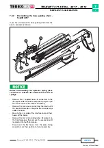
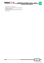
6.7
TECNORD CONTROL UNIT CONNECTIONS
1
B
8
7
5
3 4
6
2
C
J2
A
A
B
C
8
J1
2
3
4
6
5
7
1
1C
= fork rotation signal
2C
= boom up/down signal from platform
3C
= movement selector button (+12 V with white
button pressed down)
4C
= potentiometer common line (+5V)
5C
= ground
6C
= right outrigger down
7C
= feet down signal (+12V with outriggers
lowered to the ground)
8C
= platform overload signal
Summary of Contents for TELELIFT 3713 Elite
Page 4: ...Courtesy of Crane Market...


