background image

Connection methods - Telnet

1. Start 

the 

Run utility program (in Windows by choosing -> 

 Start/Run...).
 

Wait until the following “Run” window appears on the screen 


(see picture 31).

2. Write 

Telnet and click 

 button to continue. 


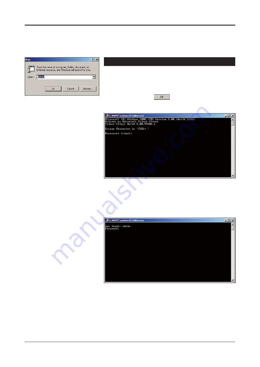
The following “Telnet.exe” window appears on the screen 
(picture 32).

Picture 31

Run utility program view.

Picture 32. Telnet program view.

3.  Enter the following command to the Telnet prompt:
 

open [IP address], where the IP address is the target 


device’s IP address.


The following “Telnet.exe/

ipx login:

” window appears on the 

screen (picture 33).

Picture 33

Telnet program view.

4.  Enter the required user name and the password 
 

(see table 8 on page 8 for User groups).


The Telnet connection to BLUEbox device is now completed 
and you can now use the CLI commands to controlling the 
device. The Telnet display is identical of local CLI view and 


as well the command structure follows the same rules as 

 local 

CLI connection.

5. The 

Telnet connection can be terminated by entering 

 command 

quit.

22 

BLUEbox series CLI user manual rev002

Summary of Contents for EASI IP Series

Page 1: ...EASI IP Series User Manual BLUEbox MPEG 2 encoder decoder BLUEbox user manual 59300233 rev002 ...

Page 2: ...al information page 11 Network configuration page 12 Video configuration page 13 Video management page 14 SAP management page 15 Video statistics page 16 Change password User management page 17 Services page 18 Data channel 1 3 pages 19 Data channel statistics page 20 Command Line Interface CLI 21 Connection methods Hyper Terminal 21 Connection methods Telnet 22 How to use the CLI 23 CLI levels 23...

Page 3: ...EG 2 video compression engine compliant with the ISO IEC 13818 2 standard Audio is compressed in the same direction with video as described in ISO IEC 11172 3 MPEG 1 audio compression standard General purpose asynchronous data channels are transferred separately from encoded video and audio signals Software version Device functional and operational suitability described in this manual is for softw...

Page 4: ...etwork to port 10 100Base Tx in the rear panel Note You can create a local WebUI connection by this connector using an Ethernet cable e g OPUS1CCC0050X cross connection cable Create management connection to the device either by over an Ethernet network or by a Mgmt port and then set all necessary settings in the device Default network addresses for the devices are are the following BBE 10 9 96 10 ...

Page 5: ...There is three dual colour leds on the front panel video led indicates state of video link led indicates state of Ethernet connection and module led indicates state of hardware The video link and module indicators on the front panel should lit green in normal operation If the led indicator is red or yellow the function in question has a error and is giving an alarm Picture 1 BBE Mpeg 2 Encoder con...

Page 6: ...eo led on the front panel is green If the video signal is missing or it s level is too low the video led is yellow Audio Connections The audio connectors 1 2 provide one uni directional audio channel line BBE BBD The audio impedance is constant and cannot be adjusted The audio input impedance is 10 kΩ and the output impedance is 10 Ω The connector is type RJ 45 female see picture 4 and table 1 for...

Page 7: ...of WebUI or CLI The connector is type RJ 45 female see picture 5 and table 2 for detailed description Table 2 Data connector s pinout and supported data types Pin RS232 RS422 RS485 2w RS485 4w 1 out in out out 2 out out in out out 3 in in out in 4 5 Ground Ground Ground Ground 6 in in in out in 7 8 Ground Ground Ground Ground Data Picture 5 Data connector BLUEbox series user manual rev002 5 ...

Page 8: ...ation by means of any terminal type program e g Windows Hyper Terminal Management software for BLUEbox devices is a Command Line Interface see page 21 for detailed description The Mgmt connector is type RJ 45 female see picture 6 and table 3 for detailed description The management cable is type CIC504 see table 7 on page 8 for pinouts Picture 6 Management connector Table 3 Mgmt connector s pinout ...

Page 9: ...t panel is green If the Ethernet signal is missing or it s level is too low the link led is yellow Note It is also possible to create Web User Interface WebUI connection locally into the device via this Ethernet connector Table 6 Ethernet connector s led 2 indicator lights Picture 7 Ethernet connector CAT5 Table 4 Ethernet connector s pinout CAT5 Pin Signal 1 Tx 2 Tx 3 Rx 4 5 6 Rx 7 8 Led Colour E...

Page 10: ...sed Locally via Mgmt connector with a serial connection cable CIC504 and any terminal emulation type program e g Hyper Terminal or Remotely via TCP IP connection e g Telnet The command structure is the same for both session types See page 21 for detailed description PC PSION D9 female RJ 45 male BLUEbox Receive data 2 2 MGMT output Transmit data 3 6 MGMT input System ground 5 1 Ground Table 7 RS23...

Page 11: ...ture 10 The Web User Interface has the following configuration display pages that are introduced in this document General Information Network Config Configuration Video Management SAP Management Statistics video statistics only in BLUEbox Decoder Change Password User Management Services Data Channel 1 Data Channel 2 Data Channel 3 Statistics data channel statistics The information on configuration...

Page 12: ...in to continue Enter Network Password window appears on the screen picture 9 Write the required username and password in the fields and then click OK button to continue Web User Interface s General Information page appears on the screen picture 10 11 The Web User Interface session to BLUEbox device is now completed User Groups for WebUI There are four different groups of authority which are determ...

Page 13: ... side of page picture 10 11 On this page you can see device s general settings and change device s hostname Hostname User definable alias name for the device uniquely identifies each device of a network Click ppl button to confirm a hostname for the device SW Version Device software version Hardware Device hardware type HW Version Device hardware version Bootloader Version Device bootloader versio...

Page 14: ...signed to be able to continue with WebUI session Netmask Mask for subnet definition Gateway Gateway address for router definition Gateway address is necessary for multicasting video Device and gateway addresses should be in the same network Note Gateway address should be set before enabling multicast video Ethernet MAC Device MAC address Speed Network connection speed Duplex Network connection typ...

Page 15: ...ther PAL or NTSC Video PID MPEG 2 video PID value This number has to be same at both encoder and decoder pairs Audio PID MPEG 1 Audio PID value This number has to be same at both encoder and decoder pairs PCR PID MPEG 2 PCR PID value PMT PID MPEG 2 PMT PID value BBE Low Latency Mode Video latency setting When enabled it reduces the switching time between different video sources i e camera touring ...

Page 16: ...re transmitting the unicast video to the same BBD decoder Respectively the unicast filtering must be enabled on BBD decoder BBD Filtering Service Filtering service enabled disabled When enabled the BBD decoder will be locked to the first received unicast video stream Respectively the unicast filtering must be enabled on BBE encoder Accepted Video Source IP Address Defined source IP address If left...

Page 17: ...tisements number of hops between routers Should be 255 as described in RFC 2974 only in BBE Announcement Interval s SAP timing in seconds Retransmit time of SAP packet This time has to be same at both encoder and decoder pairs Session Name The name of the stream associated with SAP packet This name shows at the decoders SAP page only in BBE Session Info Owner of the stream User can use own ID to d...

Page 18: ... stream settings Video state Display received video state active waiting inactive error Detected bitrate Display received video bitrate Detected video Pid Display received video pid value Detected audio pid Display received audio pid value Detected pcr pid Display received pcr pid value Rx frames Display total number of received frames Picture 20 Video statistics page only in BBD 16 BLUEbox series...

Page 19: ...ent To access user management functions admin level access rights are needed To change the user information first click heading User Management under the Administration menu on the left column Administration user management window appears on the right side of page picture 22 On this page you can add remove users and change their passwords To add a new user first type the desired user name next to ...

Page 20: ...t by ticking the checkbox before username Click button to remove user Note Always click Apply button to activate settings Services To reboot or restart the device first click heading Services under the Administration menu on the left column Administration services window appears on the right side of page picture 24 Click button to reboot the device this takes 90 seconds Click button to restart the...

Page 21: ...number has to be same at both client and server pairs Time To Live IP packets Time to live value can be set 1 to 255 Data Bits Byte length Options are 5 6 7 8 9 The default value is 8 Note In case of using parity bits they must be included here i e 8 x data 1 x parity 9 Stop Bits Options are 1 or 2 The default value is 1 Baud Rate Datachannel connection speed range 1200 115 200 bps COM Port Mode C...

Page 22: ... 2 and 3 statistics window appears on the right side of page picture 26 Rx bytes Number of bytes received since the last counter reset start up Tx bytes Number of bytes transmitted since the last counter reset start up Picture 26 Data channel statistics page BBD 20 BLUEbox series WebUI user manual rev002 ...

Page 23: ...30 without text 4 To activate the terminal connection first press Enter ipx login appears on the screen Enter the required user name and the password see table 8 on page 8 for User groups The terminal connection to BLUEbox device is now completed and you can now use the CLI commands to management the device The Hyper Terminal connection can be terminated by selecting File Exit Alt F4 or clicking x...

Page 24: ...s where the IP address is the target device s IP address The following Telnet exe ipx login window appears on the screen picture 33 Picture 33 Telnet program view 4 Enter the required user name and the password see table 8 on page 8 for User groups The Telnet connection to BLUEbox device is now completed and you can now use the CLI commands to controlling the device The Telnet display is identical...

Page 25: ...nly in BBD Config line Terminal view settings editing level Displays a list of available commands of level in question command Displays an info of the command in question command space Displays options of the command in question end Jump back to enable level exit Jump to previous level on enable level jump to start quit Jump to previous level on enable level jump to start Command Description Table...

Page 26: ...nds enable en Activate enable level exit ex Terminate CLI session help h Additional help ping p IP address Ping IP address CTRL C stop ping quit q Terminate CLI session show version s v Display device s hardware software versions a serial number and boot counter IPx enable Turn on privileged mode command exit Exit current mode and down to previous mode help Description of the interactive help syst...

Page 27: ...ernet s i f Display Ethernet status show rmon alarm s rm a Display configured RMON alarms show rmon alarm s rm e Display configured RMON events show running config s ru Display device s current settings show sap s s Display SAP settings show transport stream s t Display video settings show users s u Display video unicast filtering status show version s v Display device s hardware and software vers...

Page 28: ...move specify host to receive snmp notifications no username n u username Remove user account no username n u username password Remove user account s password no video destination polling n v d Disable destination polling quit q Back to enable level rmon Set rmon functions see separate document snmp server host s n h address Set specify host to receive SNMP notifications username name group group u...

Page 29: ...s Set destination IP address or multicast group ip port i p 1024 65535 Set IP port to receive send data ip time to live i t 1 255 Set time to live TTL value no ip n i a IP address Clear destination IP address or multicast group no shutdown n s Enable data channel service quit q Back to config level shutdown sh Disable data channel service signaling si mode Set the signaling type to RS232 rs 2 RS42...

Page 30: ...unication to half duplex operation end en Back to enable level exit ex Back to config level ip address i a IP address subnet mask gateway gateway Set IP address subnet mask and gateway for Ethernet interface ip address dhcp i a d Device gets its IP address from the DHCP server quit q Back to config level speed 10 s 10 Set Ethernet port speed to 10 Mbps speed 100 s 100 Set Ethernet port speed to 10...

Page 31: ...ive i t 0 255 Set multicast time to live value no shutdown n s Enable SAP quit q Back to config level send interval sen 3 240 SAP announcement interval session info session i text Max 30 characters describing session information session name session n text Max 30 characters describing session name shutdown sh Disable SAP Picture 40 Config sap level s view BBE IPx config sap end End current mode an...

Page 32: ...o PID pid pcr p pc 0 8191 Set PCR PID pid pmt p pm 0 8191 Set PMT PID pid video p v 0 8191 Set video PID quit q Back to config level shutdown s Disable video encoding decoding test picture always on t a Enable test picture test picture on error delay t o 1 65535 Delay for enabling test picture in seconds when video is missing video bitrate v b bitrate Set video stream bitrate to 3000 3 4000 4 5000...

Page 33: ...enable level exit ex Back to config level ip address i a IP address Unicast IP address to accept by filtering service quit q Back to config level no ip n i Clear IP parameters no shutdown n s Enable video filtering service shutdown s Disable video filtering service Picture 42 Config filter level s view only in BBD IPx config filter end End current mode and down to previous mode exit Exit current m...

Page 34: ... in sec Sets the exec timeout in minutes and secunds exit ex Back to config level no exec timeout n e Clears the exec timeout no terminal length n t l Disables text pausing quit q Back to config level terminal length t l number Number 0 512 of text lines on the screen 0 for no pausing Picture 43 Config line level s view IPx config line end End current mode and down to previous mode exec timeout Se...

Page 35: ...dress automatically rather than having it entered manually Ethernet Specified in a standard IEEE 802 3 10BASE T Ethernet systems provide transmission speeds up to 10 Mbps Fast Ethernet or 100BASE T provides transmission speeds up to 100 megabits per second and is typically used for LAN backbone systems supporting workstations with 10BASE T cards Gigabit Ethernet provides an even higher level of ba...

Page 36: ...ted individuals and or workgroups typically within a single building or over a group of neighbor ing buildings LANs are a group of computers and associated devices that share a common communi cations line and typically share the resources of a single processor or server within a small geographic area for example within an office building Usually the server has applications and data storage that ar...

Page 37: ... Allows manipulation of objects within the video stream addition subtraction object manipulation etc MTU Maximum Transmission Device The largest possible device of data that can be transmitted between a source and a destination Note that a distinction must be made between the MTU for a physical medium segment a path and for protocols For example Ethernet has an MTU of 1500 bytes while FDDI has an ...

Page 38: ...I Program Specific Information Information that keeps track of the different pro grams in an MPEG transport stream and in the elementary streams in each program PSI includes PAT PMT NIT CAT ECM and EMM PMT Program Map Tables The tables in PAT that point to video audio and data content of a transport stream PCR Program Clock Reference The sample of the encoder clock count that is sent in the progra...

Page 39: ...ations similar to where RS422 is used RS485 has the added advantage of allowing up to thirty two 32 multi dropped receivers or transmitters on a multi dropped network or bus Furthermore RS485 also permits a wire saving 1 2 duplex mode Scalability A characteristic of MPEG2 that provides for multiple quality levels by providing layers of video data Multiple layers of data allow a complex decoder to ...

Page 40: ...ing that error processing and retransmission be handled by other protocols Unicast Communication between a single sender and a single receiver on a network Streaming content can be sent unicast from one server to one user Compare with Multicast VBR Variable Bit Rate A term that describes how video or audio is encoded Variable bit rate provides a specified throughput capacity but data is not sent e...

Page 41: ...EASI is trademark of Teleste Corporation WEEE directive Directive 2002 96 EC of the European Parliament and of the Council on waste electrical and electronic equipment WEEE obliges that producers appropriately mark electrical and electronic equipment with the symbol indicating separate collection This obligation applies to the equipment put on the market in EU after 13 August 2005 Teleste devices ...

Page 42: ...MS 0 775 V 0 dBm Input impedance 10k ohm Encoding decoding MPEG 1 layer 2 ISO IEC 11172 3 Connectors RJ 45 female x 2 balanced 4 wire Data Number of channels 3 full duplex Transport TCP IP unicast and UDP IP multicast Standard RS232 422 485 selectable Bit rate up to 115 kbps standard speeds Format asynchronous standard framings Connectors RJ 45 female x 3 Management CLI RS232 local via mgmt port r...

Page 43: ...BLUEbox series user manual rev002 41 ...

Page 44: ...www teleste com ...

Reviews: