V.3600
2-1
Chapter 2
Installation
This chapter provides information on mechanical and electrical
installation of the modem.
Electrical Installation
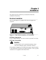
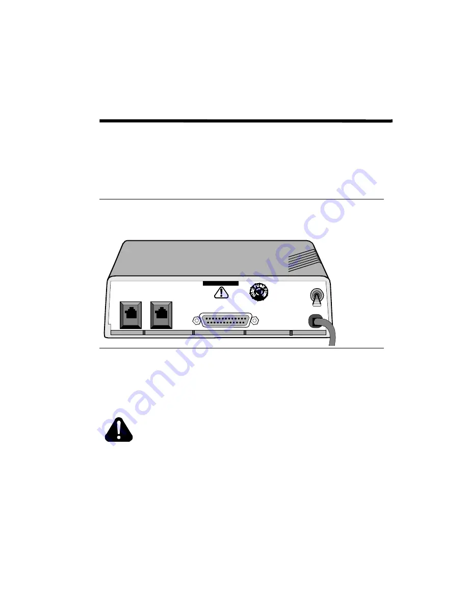
The rear panel (Figure 2-1) includes DTE cable and telephone line
connectors.
Figure 2-1. Rear Panel Connections (115 Vac Model)
AC Power Connection
Power is supplied through a 6-foot line cord with a grounded 3-wire plug.
DC Power Connection
Caution
To protect the DC-to-DC converter from damage, ensure
the positive and negative leads are properly connected.
If the modem is equipped for 12-60 VDC power input, connect the power
to the terminal block attached to the modem back panel. A chassis ground
connection is also supplied on the terminal block.
1
0
3/16
AM P S.B.
DTE
DIAL
TELSET
LEASED LINE
115 VAC
60 HZ
1/4 AM P
Summary of Contents for V.3600 Series
Page 3: ...Copyright V 3600 iii...
Page 9: ......
Page 10: ...x V 3600 Regulatory Information...
Page 20: ...Contents continued xx V 3600 Appendix I Country Specific Parameters Service and Support...
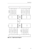
Page 29: ...Installation V 3600 2 3 Figure 2 2 Digital Interface Signals...
Page 36: ......
Page 42: ......
Page 54: ......
Page 100: ......
Page 112: ......
Page 194: ......
Page 196: ......
Page 204: ......
Page 236: ......
Page 258: ......


