background image

Maintenance

12-2

V.3600

Before attempting diagnostic tests, verify that all connectors and plugs 
are firmly inserted. The test procedures identify the faulty component in 
a bad communications link.

Calling Technical Support

The Service and Support page at the back of this User’s Guide contains 
several phone and faxback numbers and the Web address. If calling 
Technical Support, please call from a location near the computer with 
the modem. It helps expedite the call to have the following information 
available:

• Type of modem -- V.3600
• Modem serial number
• Date code
• Purchase date
• Type and version of software, including data communications, 

fax, and browser/reader software

• Type and version of other software running at the same time

Note

Do not return the modem to the manufacturer without prior 
authorization. 

If the unit appears faulty, contact Telenetics at (949) 455-4000 (USA) or 
through our Web site at http://www.telenetics.com for service and 
assistance. 

Summary of Contents for V.3600 Series

Page 1: ...V 3600 Modem User s Guide TeleneticsxCorporation Part No TEL T0097 BB 25111 Arctic Ocean Model V 3600 Lake Forest California 92630 USA 2002 Telenetics V 3600 CS RS TD RD Cd TR YES NO TALK DATA...

Page 2: ...information contact Telenetics Corporation 25111 Arctic Ocean Lake Forest California 92630 USA Tel 949 455 4000 Trademarks Telenetics is a registered trademark of Telenetics Corporation The fol lowing...

Page 3: ...Copyright V 3600 iii...

Page 4: ...phone company to determine the maximum REN for your calling area A variety of Universal Service Ordering Code USOC telephone wall jacks are available for different types of devices or services The USO...

Page 5: ...tion of the business or other entity or other individual sending the message and the telephone number of the sending machine or such business other entity or individual Programming of this information...

Page 6: ...cording to the instruction manual It has been tested and complies with the limits for a Class A computing device according to FCC Rules Part 15 Operation of this equipment in a residential area may ca...

Page 7: ...talling this equipment users should ensure that it is permissible to be connected to the facilities of the local telecommunications company The equipment must also be installed using an acceptable met...

Page 8: ...only to the requirement that the sum of the Ringer Equivalence Numbers of all the devices does not exceed five 5 CANADIAN EMISSION REQUIREMENTS V 3600 115 Vac This Class B digital apparatus meets all...

Page 9: ......

Page 10: ...x V 3600 Regulatory Information...

Page 11: ...one Line Connection 2 6 Dial Mode PSTN Connection DIAL jack 2 6 Leased Line Connection TELSET LEASED LINE Jack 2 7 Shelf Mount RM16M V 3600 Installation 2 9 Chapter 3 Getting Started Option Selection...

Page 12: ...nect Speed Messages X 5 7 Number Code Application RC 5 8 Response Number Codes Messages 5 9 Dial Commands 5 13 Dialing D 5 13 Tone Dialing T 5 14 Pulse Dialing P 5 14 Insert Long Pause 5 14 Wait for S...

Page 13: ...L 5 29 Auto Retrain E 5 30 Automatic Rate Adaption R 5 30 Manual Rate Adaption RR 5 31 Product Revision Level V 5 31 Online Quick Reference H 5 32 Product Serial Number V 5 32 Talk Data DA 5 32 V 32...

Page 14: ...Mode 6 2 Direct Mode 6 3 Flow Control 6 3 Protocol Commands 6 3 Disconnect Buffer Delay Q D 6 4 Serial Port DTE Constant Speed J 6 4 V 42 Optional Detection Phase M 6 5 Operating Mode N 6 5 Auto Relia...

Page 15: ...4 High Security 8 4 Compatibility 8 4 Capacity 8 5 Operating without High Security 8 5 Operating with High Security 8 5 Security Levels 8 5 Level 1 Password Only 8 5 Level 2 Password with Callback 8...

Page 16: ...ile Receive FRM Mod 9 8 HDLC Transmit FTH Mod 9 9 HDLC Receive FRH Mod 9 9 Test Supported Range of Values FTx FRx 9 9 Class 1 Result Code FCERROR 9 10 Fax Autoanswer FAA 9 10 DTE Autobaud for Fax Auto...

Page 17: ...Time S42 10 15 S43 10 15 XON Character from DTE S44 10 15 XOFF Character from DTE S45 10 15 S46 48 10 15 XON Character to DTE S49 10 15 XOFF Character to DTE S50 10 15 Dial Line Transmit Level S51 10...

Page 18: ...2 Software Guidelines 11 2 Invalid Responses 11 3 Dial Parameters 11 4 V 25 bis Commands and Responses 11 5 Dial Command CRN nn n 11 5 Program Number Command PRN a nn n 11 6 Intermediate Call Progress...

Page 19: ...ve Ring Commands E 12 Fax Commands E 12 Class 1 Commands Valid in Only Fax Mode E 12 Security Commands E 14 Remote Configuration Commands E 16 Status Registers E 17 V 25 bis Dialer Commands E 20 V 25...

Page 20: ...Contents continued xx V 3600 Appendix I Country Specific Parameters Service and Support...

Page 21: ...connected to similarly equipped computers computer services and data bases Advanced error control and data compression ensure data integrity and increase data throughput When used with a Class 1 Fax s...

Page 22: ...T V 34 CCITT V 33 CCITT V 32 bis CCITT V 32 CCITT V 29 CCITT V 27 CCITT V 22 bis CCITT V 22 CCITT V 21 CCITT V 13 Bell 212A Bell 103 Compatible with a variety of software packages Synchronous operatio...

Page 23: ...Standard Class 1 interface conforms to EIA 578 Group 3 compatibility CCITT V 21 Channel 2 V 27 ter V 29 V 17 Autoanswer under software control Automatic fax data detection Software Software operates t...

Page 24: ...Built in test features can determine system performance and isolate faults in the data link Operation and configuration are controlled by the front panel LCD the AT command set or the V 25 bis command...

Page 25: ...ear panel has an EIA 232 DTE connector an 8 pin TELSET LEASED LINE jack an 8 pin DIAL jack the power switch fuse and cord Figure 1 2 Figure 1 2 Rear Panel 115 Vac Model 1 0 3 16 AMP S B DTE DIAL TELSE...

Page 26: ...Figure 1 3 has edge connectors that insert into the shelf backplane The shelf backplane performs the same functions as the standalone rear panel Refer to the Shelf Mount RM16M V 3600 Installation sec...

Page 27: ...Connection Power is supplied through a 6 foot line cord with a grounded 3 wire plug DC Power Connection Caution To protect the DC to DC converter from damage ensure the positive and negative leads ar...

Page 28: ...connector A chassis ground connection is also supplied on the terminal block DTE Connection The DTE connector is a 25 pin D series type conforming to EIA 232 specifications You must use a shielded DT...

Page 29: ...Installation V 3600 2 3 Figure 2 2 Digital Interface Signals...

Page 30: ...Async data does not require a receive clock 4 CA 105 Requestto Send A positive level to the modem when data transmission is desired 5 CB 106 Clear to Send A positive level from the modem in response...

Page 31: ...ways be active high in 2 wire private line operation Cycling DTR causes retraining 21 140 Remote Digital Loopback A positive level causes a digital loopback test mode at the remote modem 22 CE 125 Rin...

Page 32: ...PSTN Connection DIAL jack The public switched telephone network PSTN is a two wire dial network Modems are registered with the Federal Communications Commission FCC for direct connection to the PSTN...

Page 33: ...elded DTE Cable 8 pin Connectors DTE Connector Screws Use 8 pin Modular at modem end to 6 pin Modular at RJ11 wall jack end connector Cable supplied with telephone EIA 232 25 Pin Connector to DTE 1 Th...

Page 34: ...ck end connector Optional connection for dial backup use Leased Line Cable EIA 232 25 Pin Connector to DTE 1 Set the transmit output level to 0dBm 2 DTR which is the signal on pin 20 of the DTE interf...

Page 35: ...ount installation The unit has an edge connector that inserts into a receptacle located on the backplane and power bus Note Figure 2 5 represents a typical dialup connection using one of the most comm...

Page 36: ......

Page 37: ...ers A second series of special ATS commands allows the user to change single bits within a byte to change an option Chapter 10 also explains single bit control Software Program A wide variety of softw...

Page 38: ...advance to Main Menu 6 CHANGE PHONE NUMBER 2 Enter the number by using the NO pushbutton to scroll the menu and YES to select 3 After the number is entered press YES to store the number 4 Advance the...

Page 39: ...and place the modem in the data mode Answering from Terminal with AT Command Set The modem displays the ring response To answer a call type ATA The modem sends an answer back tone and attempts to conn...

Page 40: ...GO TO TALK When YES is pressed modem hangs up if no telephone is connected or if the connected telephone is not off hook Pressing NO displays DO YOU WANT TO DISCONNECT Press YES to disconnect Train Ti...

Page 41: ...th dial backup enabled extended loss of carrier or 4 unsuccessful retrains in 3 minutes causes dial backup Test Mode entered Certain test modes require call termination Modem power is turned off Table...

Page 42: ......

Page 43: ...dy TR lights when the DTE asserts Data Terminal Ready This signal is input on pin 20 CCITT V 24 108 2 CS Clear to Send CS lights when the modem is ready to send data to the DTE This signal is output o...

Page 44: ...specific items in the third column The fifth and sixth columns in the table show associated AT commands and S registers as a cross reference Each column item has a corresponding header in the previous...

Page 45: ...AY STATUS PROTOCOL NONE MNP 2 3 4 5 LAPM DISPLAY STATUS COMPRES SOR NONE MNP 5 V 42b DISPLAY STATUS CARRIER DESCRIP TIONS RECEIVE LEVEL NEAR END ECHO LEVEL FAR END ECHO LEVEL FAR END ECHO DELAY FREQUE...

Page 46: ...ED DIAL LINE CHANGE MODULATION 2 WIRE 4 WIRE L1 L S27 AUTO MODE V 21 BELL 103 B212A V 22 bis V 27 ter V 29 V 33 V 32bis V 34 MM MM1 MM2 MM4 MM5 MM6 MM8 MM10 MM11 MM12 S88 CHANGE MAX DCE RATE 33600 312...

Page 47: ...L3 L2 L1 L S69 CHANGE V 34 RATE THRESH OLD LOW BER MED BER HIGH BER TH TH1 TH2 V 34 ASYM RATES ENABLE DISABLE AS1 AS S96 NORMAL ORIGINATE FORCED ANSWER NORMAL ORIG FORCED ANS OR OR1 S14 V 22 GUARD TO...

Page 48: ...ENT DISCONNECT OFF SHORT LONG LC LC1 LC2 S32 LONG SPACE DISCONNECT ENABLE DISABLE Y1 Y S21 DIAL BACKUP MANUAL AUTO MATIC DB DB1 S32 LOOKBACK TIME 0 DIS ABLED to 255 MINUTES S28 CHANGE PROTOCOL OPTIONS...

Page 49: ...4 Q5 Q6 Q7 S54 XON XOFF PASS THROUGH ENABLE DISABLE X1 X S54 INACTIVITY TIMER OFF 15 30 45 60 75 90 MIN TLn S58 BREAK OPTION 0 1 2 3 4 5 K K1 K2 K3 K4 K5 S59 V 42 FAST DETECT ENABLE DISABLE M1 M S70 C...

Page 50: ...OMMAND SET ENABLE DISABLE NT1 NT S29 CHARACTER TYPE V 25 only ASCII EBCDIC S30 SDLC DATA FORMAT NRZ NRZI S30 DTR STATE IGNORE RECALL CMD DISCON NECT RESET D D1 D2 D3 S21 DSR STATE NORMAL FORCED HIGH O...

Page 51: ...ST ENABLE DISABLE LA1 LA S34 DTE REMOTE TEST ENABLE DISABLE RD1 RD S34 REMOTE COM MANDED ENABLE DISABLE T4 T5 S23 TEST TIMEOUT OFF 60 120 180 240 SEC S18 CHANGE DIAL OPTIONS DIAL TYPE PULSE TONE P T S...

Page 52: ...1 9 Fn n 1 9 LOAD USER OPTION SET 1 2 Z0 Z1 STORE PRESENT OPTIONS 1 2 W W1 USER OPTION AT RESET 1 2 Y Y1 6 CHANGE PHONE NUMBERS PHONE NUMBER ENTER NUMBER 32 digits Zx n n phone and modifi ers CNx n 7...

Page 53: ...returns to Main Menu 1 and the front panel is secured In secured state the Main Menu 1 screen continues to maintain modem status but a password must be entered before other front panel screens may be...

Page 54: ......

Page 55: ...of command statements Response page 5 5 Dial page 5 13 Answer page 5 17 Terminal Interface page 5 19 General page 5 22 Private Line page 5 33 Configuration page 5 37 Remote Configuration page 5 41 Oth...

Page 56: ...a but does not accept or execute command instructions Example The modem is in the command state The D command and phone number are used to dial a remote modem The local modem waits to receive an answe...

Page 57: ...was accepted or giving the data requested by the command line To clear command statements from the buffer you can Turn the modem off Enter AT or Use the DTR reset feature Data Terminal Ready D sectio...

Page 58: ...ity are not counted For example the modem reads the commands ATD 212 554 1212 ATD2125551212 ATD 212 555 1212 as having 11 characters each Commands can be typed in any of these forms Backspace Key Use...

Page 59: ...ears in the command statement reading from left to right For example the command statement ATQ0V0L3DT5551212 means AT Attention Q Allow response messages to be sent V Select digit code responses L3 Se...

Page 60: ...otiation status displays to alert the user to the link rate protocol and DTE rate Connect Message Codes V The V 3600 AT V command provides the following connect message options Command Operation V Ena...

Page 61: ...returns an appropriate CONNECT message or code to the screen The modem does not detect a busy or no dial tone situation The X2 command followed by a dial command makes the modem go off hook and wait f...

Page 62: ...rns a BUSY message and hangs up If the call is completed the appropriate CONNECT message similar to X1 is displayed The X4 command combines the features of X1 X2 and X3 The factory setting is X4 Note...

Page 63: ...Command not recognized or too long 5 CONNECT 1200 Connection made at 1200 bps 6 NO DIAL TONE No dial tone detected for 5 seconds X2 or X4 command in effect 7 BUSY Dialed number busy X3 or X4 command...

Page 64: ...connection 42 CONNECT 4800 V42bis V 42 bis 4800 bps connection 43 CONNECT 7200 V42bis V 42 bis 7200 bps connection 44 CONNECT 9600 V42bis V 42 bis 9600 bps connection 45 CONNECT 12000 V42bis V 42 bis...

Page 65: ...V 42 4800 bps connection 65 CONNECT 7200 V42 V 42 7200 bps connection 66 CONNECT 9600 V42 V 42 9600 bps connection 67 CONNECT 12000 V42 V 42 12000 bps connection 68 CONNECT 14400 V42 V 42 14400 bps c...

Page 66: ...ion 93 CONNECT 21600 MNP5 MNP5 21600 bps connection 94 CONNECT 24000 MNP5 MNP5 24000 bps connection 95 CONNECT 26400 MNP5 MNP5 26400 bps connection 96 CONNECT 28800 MNP5 MNP5 28800 bps connection 97 C...

Page 67: ...nection 114 CONNECT 19200 MNP MNP 19200 bps connection 115 CONNECT 21600 MNP MNP 21600 bps connection 116 CONNECT 24000 MNP MNP 24000 bps connection 117 CONNECT 26400 MNP MNP 26400 bps connection 118...

Page 68: ...ed Pulse Dialing P To pulse dial a number sequence insert a P in the dial sequence AT D P 554 9902 Insert Long Pause To insert a long pause in the dialing sequence use a comma This inserts a 2 second...

Page 69: ...l tone dials the phone number pauses flashes to start the transfer pauses a second time then uses 7 to transfer the call to extension 377 Switching to Answer Mode after Dialing R To switch to answer m...

Page 70: ...to the requirements of the banking service Dialing a Stored Telephone Number Sn To dial one of the previously stored numbers enter Sn where n represents a stored telephone number location between 1 an...

Page 71: ...y entering ATA when the phone rings Autoanswer S0 Autoanswer is controlled by register S0 S0 determines which ring the modem answers on S0 can be loaded with a value between 1 and 255 for autoanswer E...

Page 72: ...s providing distinctive ring service to the local phone line the V 3600 can report the type of ring to the DTE The data communications software package must allow distinctive ring Caller ID and Distin...

Page 73: ...rminals and other devices require DCD on in order to communicate with the modem if so use the C command Note AT C3 is used to simulate switched carrier operation Command Operation DR 0 Disable Distinc...

Page 74: ...ialer is selected selecting DTR active will cause an autodial after an off to on transition of DTR Command Operation S DSR always on S1 DSR on when off hook in data mode S2 DSR off for 5 seconds after...

Page 75: ...when carrier is detected R9 forces CTS to follow the state of RTS without delay Note RTS CTS delay is not valid in buffered mode or with error control enabled Note With R2 selected XON XOFF is the onl...

Page 76: ...escape character three times is the default Pause for the length of time set by register S12 1 second is the default before and after the to ensure the modem recognizes the escape command This sequenc...

Page 77: ...mand to take the modem off hook The modem automatically goes off hook when a dial command is keyed in Fast Disconnect H2 H3 The results of the H command can be modified by the H2 and H3 commands H2 or...

Page 78: ...form Enter the I3 command to request the product version Speaker Volume L The L commands offer three volume levels Speaker Control M The M commands enable or disable the speaker for monitoring purpose...

Page 79: ...ng This signals the remote modem to disconnect The local modem will disconnect if it receives 1 6 or more seconds of data space condition from a remote modem If break sequences of 1 6 or more seconds...

Page 80: ...on M Async data dialer mode V 25 bis disabled M1 Sync data mode async dialer M2 Sync data mode DTR dials if active M3 Sync data mode manual dial M4 Sync data mode ASCII with V 25 bis BISYNC dialer M5...

Page 81: ...the modem to run different bit rates on the receiver and transmitter Modulation MM The MM command sets the current modulation type to use when attempting to make a connection Using this command autom...

Page 82: ...t a speed different from DTE speed enter the Bn command where n 1 to 18 MM5 V 22 bis MM6 V 27 bis 4 wire leased only MM7 Reserved MM8 V 29 4 wire leased only MM9 Reserved MM10 V 33 4 wire leased only...

Page 83: ...speed it disconnects the link automatically Valid for V 32 bis modulation only B16 28800 bps B17 31200 bps B18 33600 bps Command Operation L Disabled L1 Disabled L2 1200 bps L3 2400 bps L4 4800 bps L...

Page 84: ...sabled factory default low BER 1 in 105 medium BER 1 in 104 high BER 1 in 103 The following guidelines apply to automatic rate adaption Automatic rate adaption is disabled during direct mode Manual ra...

Page 85: ...Enable automatic rate adaption using medium BER 1 in 104 R3 Enable automatic rate adaption using high BER 1 in 103 Command Operation RR Rate adaption to 2400 RR1 Rate adaption to 4800 RR2 Rate adapti...

Page 86: ...limited distance dial or 2 wire leased lines Incoming Call IC The IC command makes the modem disregard an incoming call Line Current Disconnect LC Dial line operation only The modem can be configured...

Page 87: ...e Both modems should have only one protocol MNP or LAPM enabled and Protocol Fallback must be disabled DCE line speed must be the same for both modems 4 Wire Operation In 4 wire operation the modem is...

Page 88: ...When connected via leased line the modems will connect and begin communicating with each other The L command is used to select private line leased line operating mode The OR commands select the origin...

Page 89: ...begin communicating over the dial up line If the dial connection is unsuccessful after three attempts a retrain on the leased line will be initiated In manual mode the return to leased line is only d...

Page 90: ...dial backup selected Available in leased line operation only Answer Originate OR OR forces the modem to answer or originate mode This option is used during 2 and 4 wire leased line operation with err...

Page 91: ...ons and functions Any active profile option can be changed to meet an immediate requirement The active profile is maintained in volatile memory referred to as S registers Stored Profile When an active...

Page 92: ...s off or until W is issued with a new configuration Figure 5 1 Configuration Storage and Recall Powerup Option Set Y The Y command determines which user option set is loaded during powerup and reset C...

Page 93: ...actory option set 1 async dial up withV 42 bis F2 Load factory option set 2 async dial up withoutV 42 bis F3 Load factory option set 3 sync dial up without V 42 bis F4 Load factory option set 4 sync 4...

Page 94: ...phone number is retained until replaced by another number Modem power can be turned off without affecting stored information To store a telephone command line in a location enter the Zx n command wher...

Page 95: ...x H Remote Configuration This mode of operation allows viewing or modifying the options of a remote modem that supports Telenetics Motorola or Motorola UDS remote configuration Remote configuration is...

Page 96: ...s may be performed as needed To exit remote configuration return DTE service to the local modem The T command will exit remote configuration mode Remote configuration may be entered immediately after...

Page 97: ...allows remote configuration by using blank as the security code Remote Configuration can also be specified by the dial command by placing T password after the dial digits the equal sign is left off F...

Page 98: ...8 Remote configuration DTE speed 14400 bps RB9 Remote configuration DTE speed 16800 bps RB10 Remote configuration DTE speed 19200 bps RB11 Remote configuration DTE speed 21600 bps RB12 Remote configur...

Page 99: ...ration Saving or Discarding Options RQ This option allows the opportunity to discard an undesirable option Command Operation RQ Save remote configuration option selection and exit RQ1 Discard remote c...

Page 100: ......

Page 101: ...requires no special hardware or software Data to be transmitted is put in a buffer so the modem can retransmit it if an error occurs The modem also buffers data received from the remote modem in case...

Page 102: ...ng the data stream and reducing the number of bits required to represent the characters 100 error free transmission is assured by the application of the MNP or LAPM error control protocol on the compr...

Page 103: ...faster than it can send them to the remote modem The modem holds characters in an internal buffer until they can be transmitted When this buffer is full the modem uses flow control to cause the DTE to...

Page 104: ...operate at different speeds The J1 command forces serial port DTE speed to follow data link speed in any mode Table 6 1 Operating Modes and Features Operating Mode Error Correction Data Compression Fl...

Page 105: ...kbps V 42 Optional Detection Phase M This is a data sequence that speeds up the LAPM link negotiation time if V 42 LAPM is supported by the remote modem Operating Mode N Select theV 42 bis mode to be...

Page 106: ...ting an ASCII character Note The modem must be set for auto reliable mode AT N3 N5 N6 N7 Command Operation N Normal mode no error control data buffered N1 Direct mode no error control data not buffere...

Page 107: ...FF characters to start and stop the data flow These characters have the same parity as the DTE setup taken from the last AT command When the Q2 command is used the modem uses CTS off to stop the data...

Page 108: ...remote system before the modem is ready to receive more data possibly resulting in data loss Data Link Flow Control G This flow control paces data from the remote modem to the local modem during a no...

Page 109: ...is in connect state during a direct connection no protocol data not buffered Command Operation K Break option 0 K1 Break option 1 K2 Break option 2 K3 Break option 3 K4 Break option 4 K5 Break option...

Page 110: ...A smaller block size maximizes throughput when marginal line conditions are causing errors The modem sends a block up to the size specified by the A command Command Operation K K1 Empty the data buffe...

Page 111: ...modems try to establish a reliable link Use these commands when the modem is in the auto reliable mode and is expected to process a call from a modem not in a reliable mode V 42bis Data Compression C...

Page 112: ......

Page 113: ...and Note Local analog loopback with or without a test pattern is the only test available in protocol mode Test Categories Diagnostic tests fall into two categories those that can be performed online o...

Page 114: ...before the T command to go to the command mode By preloading register S18 with 1 to 255 each test mode automatically times out after the specified number of seconds and exits back to the command mode...

Page 115: ...ck the modem transmitter connects to its receiver so the analog signal normally sent over the telephone line is received locally If operating on leased lines the lines are terminated into 600 ohms Fig...

Page 116: ...Loopback Figur e7 2 The modem transmits a test pattern The test pattern is looped back to the receiver and checked for errors Entering the T command causes the modem to exit Self Test Analog Loopback...

Page 117: ...d mode If not enter T to exit the test Enter the command to return to online data mode The local modem receiver connects to its transmitter so received data is retransmitted to the remote site If Digi...

Page 118: ...command to allow an RL request Enter a test message and verify the message is being looped back to your terminal screen If the message is incorrect use the analog loopback tests on both modems to iso...

Page 119: ...loopback tests to isolate the problem Figure 7 5 Local Modem Initiating Remote Digital Loopback with Test Pattern Test Pattern T In Test Pattern transmitted data from the local DTE is blocked and rep...

Page 120: ...timeout period and does not re enter the test mode until an off to on transition of pin 21 is detected DTE Controlled Local Analog Loopback Pin 18 LA To enable DTE Controlled Local Analog Loopback Tes...

Page 121: ...tion on page 8 8 Systems administrator functions cannot be accessed without this password If you forget the superuser password contact Technical Support Refer to Calling Technical Support section on p...

Page 122: ...d V 34 except for additional AT commands which allow access to security With these commands a user can set passwords and turn security on When security is enabled a password must be used to change sec...

Page 123: ...rds Two passwords of up to ten characters each can be stored in the modem s nonvolatile memory AT commands change the passwords Backspace and escape keys are not supported for password entry The passw...

Page 124: ...sword is deleted Security Reset DR This command resets security to its initial state off with no passwords stored The option is not available in remote configuration Disabling Security D x The D x com...

Page 125: ...to the secured V 3600 to use the unit If a power outage occurs the logged on user must logon again when the power is restored For optimum security operation a reliable connection should be used Securi...

Page 126: ...disables security the only security commands available are those used to enable security or to check security status Passwords Passwords can be changed or deleted by the superuser The regular user ca...

Page 127: ...ange the default SUPERUSER and USER 1 passwords as soon as possible High Security Commands These commands are only available to a local superuser Enabling High Security EH pw The EH pw command enables...

Page 128: ...of the password Passwords cannot be recalled from nonvolatile memory Note The superuser password is critical because the security feature cannot be configured without it After logon as USER 1 and gain...

Page 129: ...the local superuser has enabled the W1 option W2 A remote regular user can gain superuser privilege once the local superuser has enabled the W2 command W0 The extended feature options can be cleared b...

Page 130: ...user s illegal attempt count Enter the M command to reset all of the user s illegal attempt counts Factory Reset F pw pw To reinitialize the security feature enter the F pw pw command where pw is the...

Page 131: ...peruser privileges can check any user s information A user with superuser privileges can also display the assigned security level and callback number for each valid user within a block of ten consecut...

Page 132: ...nected to the secure modem A callback sequence or A callback with password reentry When the call is terminated from either end the secureV 3600 automatically resets itself to the secure mode for the n...

Page 133: ...Class 0 data mode or Class 1 fax mode The LCD display indicates when fax mode is enabled The V 3600 default configuration is for data mode Service Class is normally only changed by the software as nec...

Page 134: ...command when the fax software is first loaded Subsequent fax operations may not reset the fax profile and if a fax required option has been changed fax operation will not work An example of a fax ini...

Page 135: ...required reset the fax profile for the next fax transmission Class 1 Details Operation as a fax modem complies with EIA 578 details of Class 1 operation and compatibility are found in that standard T...

Page 136: ...lly issued by the fax software and not by the user They are provided here for reference While only the lower order 7 bits of each character are used for commands and parameters T 30 Phase C data trans...

Page 137: ...ns a CONNECT result code This is because dialing in fax mode FCLASS 1 implies an initial FRH 3 command described in the Fax Transmit and Receive Modes section on pa ge9 7 Answer Command A The A comman...

Page 138: ...fault setting is normally only changed by software if needed Class 1 Operation FCLASS 1 Setting the Service Class to 1 with the FCLASS 1 command configures the modem as a Class 1 fax modem This comman...

Page 139: ...5 seconds The modem aborts the command and sends an OK result code if the DTE sends an additional character which is discarded during the command execution This command returns an ERROR result code if...

Page 140: ...cation Facsimile Receive FRM Mod FRM Mod causes the modem to receive data using the modulation and speed selected with the Mod parameter If the selected carrier is detected a CONNECT result code is se...

Page 141: ...OR CONNECT ERROR result code and returns to command mode This command will be aborted if the DTE sends any character to the modem other than DC1 or DC3 during this mode For additional information cons...

Page 142: ...oanswer feature to autobaud at 19 2 kbps or greater if desired Binary File Transfer Some Class 1 software packages may provide an option for transferring files between computers with fax modems using...

Page 143: ...to perform a function The S register values comprise the configuration profile Generally the user should not directly alter S register values However the user has the option of entering S registers v...

Page 144: ...S registers must not be confused with the total register value Bit values are counted separately for each option group called bit mapping while the register value is the cumulative decimal or hexadeci...

Page 145: ...Values Sn v Sn v To change an option using ATS commands requires the operator to precalculate the revised decimal or hexadecimal total Note Because of the chance of miscalculating the bit sum causing...

Page 146: ...mand For these options the individual bit AT command can be used to change the setting of the bit controlling the option To change a single bit value within a register enter ATSn v where n register nu...

Page 147: ...red ASCII value 0 127 To disable the escape command set S2 to any value greater than 127 128 255 End of Line Character S3 The standard end of line character is the carriage return ASCII value of 13 Th...

Page 148: ...8 to change the basic pause interval 0 255 or use several commas in a row for greater delay during dialing The default value is 2 seconds Carrier Detect Time S9 S9 contains the amount of time 0 255 in...

Page 149: ...S12 contains the pause interval in 0 02 second increments The factory setting is 50 equivalent to 1 second 50 x 0 02 sec When S12 is 0 timing is not a factor The timing between the 3 escape characters...

Page 150: ...es not exist for the option the column is left blank S15 Reserved Bit Value Command Description 0 Reserved 1 0 1 E E1 Local character echo off Local character echo on 2 0 1 Q Q1 Response messages on R...

Page 151: ...0 S19 20 Not used Bit Value Command Description 0 0 1 Analog loopback inactive Analog loopback in progress 1 Reserved 2 0 1 Digital loopback inactive Digital loopback in progress 3 0 1 Remote digital...

Page 152: ...m hangs up when DTR turns off Modem resets when DTR turns off 7 0 1 Y Y1 Long space disconnect disabled Long space disconnect enabled Bit Value Command Description 1 0 00 01 10 11 L L1 L2 L3 Speaker v...

Page 153: ...TS CTS Delay S26 The S26 register specifies the amount of time 0 255 in 0 01 second 10 ms increments between the RTS signal and the CTS signal The default value is 0 7 0 1 P P1 Make break ratio US 39...

Page 154: ...sync Sync data async dial Sync data dial through DTR Sync data manual dial 2 0 1 L L1 and L2 Dial up line Leased line 3 Reserved 5 4 00 01 10 11 X X1 X2 Internal clock External clock Receive clock Not...

Page 155: ...led DTE fallback enabled Bit Value Command Description 0 Reserved 1 0 1 V 25 ASCII V 25 EBCDIC 2 0 1 V 25 VAL enabled V 25 VAL disabled 4 3 Reserved 5 0 1 NRZ V 25 NRZI V 25 7 6 00 01 10 11 M M4 M5 M6...

Page 156: ...61 Bit Value Command Description 0 0 1 L1 L2 2 wire leased line only 4 wire leased line only 1 0 1 LC1 LC2 Line current disconnect short Line current disconnect long 2 0 1 LC LC1 or LC2 Line current d...

Page 157: ...127 to be sent from the DTE The default value is ASCII 19 S46 48 Reserved XON Character to DTE S49 Select the XON character 0 127 to be sent to the DTE The default value is ASCII 17 XOFF Character to...

Page 158: ...otiation above initial connect 1 Reserved 3 2 00 01 10 11 R R1 R2 R3 Automatic rate adaption threshold disabled Low BER Medium BER High BER 4 Reserved 5 0 1 Protocol negotiation status disabled Protoc...

Page 159: ...e Command Description 1 0 00 01 10 11 C C2 C3 C1 Compression disabled Compression enabled on transmit data only Compression enabled on receive data only Compression enabled on transmit and receive dat...

Page 160: ...d Refer to the Break Control Kn section on pa ge6 9 for further information Bit Mapped S60 Bit Value Command Description 7 0 0 1 255 T Tn n 1 255 Disable Timer value in minutes Bit Value Command Descr...

Page 161: ...or ring and remains on for duration of call RI blinks for ring and turns off when call is answered 7 0 1 V V1 Disable protocol response messages Enable protocol response messages Bit Value Command Des...

Page 162: ...ce only S68 Reserved Bit Value Command Description 7 0 0 1 127 A An Disable auto reliable fallback character ASCII value 1 127 Bit Value Command Description 4 0 00000 00001 00010 00011 00100 00101 001...

Page 163: ...nnect rate is determined by S69 Bit Value Command Description 4 0 00000 00001 00011 00100 00101 00111 01000 00110 01001 01010 00010 01011 01100 01101 01110 01111 10000 10001 10010 B B1 B2 B3 B4 B5 B6...

Page 164: ...ates the level of error controlling protocol This register is for reference only Bit Value Command Description 2 0 000 001 010 011 100 101 110 111 N N1 N2 N3 N4 N5 N6 N7 Normal Direct MNP only reliabl...

Page 165: ...number of times the modem will attempt to place the callback call to a remote user if the first attempt is unsuccessful The default is 0 Bit Value Command Description 0 0 1 J J1 Disable slaved DTE DCE...

Page 166: ...seven attempts Autocallback Timer S78 The S78 register specifies the time in seconds that the modem waits before initiating autocallback The default is 30 seconds Break Length S79 The S79 register se...

Page 167: ...tion 4 0 00001 00010 00011 00100 00101 00110 00111 01000 01001 01010 01011 01100 01101 01110 01111 10000 10001 10010 10011 10100 300 bps 600 bps 1200 bps 2400 bps 4800 bps 7200 bps 9600 bps 12 000 bps...

Page 168: ...5 L16 L17 L18 Disabled Disabled 1200 bps 2400 bps 4800 bps 9600 bps uncoded 9600 bps trellis 7200 bps 12 000 bps 14 400 bps 600 bps 16 800 bps 19 200 bps 21 600 bps 24 000 bps 26 400 bps 28 800 bps 31...

Page 169: ...1001 1010 1011 1100 Auto mode V 21 B103 Reserved B212A V 22 bis V 27 lease line only Reserved V 29 lease line only Reserved V 33 lease line only V 32 bis V 34 7 4 Reserved Bit Value Command Descripti...

Page 170: ...coding 5 0 1 Disable pre emphasis Enable pre emphasis 6 0 1 Disable constellation shaping Enable constellation shaping 7 0 1 Precoding disabled Precoding enabled Bit Value Command Description 4 0 Rese...

Page 171: ...ronous Mode Selection M section on pa ge5 25 If using the LCD 1 Scroll through the menu to Main Menu 5 MODIFY CONFIGURATION 2 Advance to and enter the DTE PARAMETERS submenu 3 Select SYNC DATA 4 Advan...

Page 172: ...The a and the nnn n are both parameters Not all commands have parameters For example the CIC command has no parameter Software Guidelines An indicator enclosed in less than greater than signs represe...

Page 173: ...V 25 bis dialer w SDLC protocol sync data ASCII NRZI M11 V 25 bis dialer w SDLC protocol sync data EBCDIC NRZI Separator fields depend on the data format for ASYNC sep command CR BISYNC sep sy sy stx...

Page 174: ...s 2 Any parameter or parameter set containing no valid only ignored characters 3 Any parameter set containing an out of range parameter Dial Parameters Table 11 1 lists and describes the parameters us...

Page 175: ...r free command with no transmission error such as a parity error This confirmation is sent before the command is executed INVCU Invalid command command unknown Example TRN 205 555 0124 INVMS Invalid c...

Page 176: ...all Progress Response The following response is given only if enabled See Option Definition 002 below CNX nnnnnBPS where nnnnn is the line speed This connect response appears after handshake completed...

Page 177: ...mat the last LSN string terminates with etx per V 25 bis For synchronous bit oriented operation each LSN string is treated as an individual message per V 25 bis All stored numbers are sent to the DTE...

Page 178: ...re r is the recall count 1 r n 1 2 etc followed by a separator field and call progress messages CFI XX etc If the call fails to connect this is repeated for the specified number of times Link Number b...

Page 179: ...nses VAL Valid command received Transmitted on receiving an error free command with no transmission error such as a parity error This confirmation is sent before the command is executed INVCU Invalid...

Page 180: ...ber of failed call attempts made to the number yyy the number of minutes that calls to the number are delayed Request List of Linked Numbers RLL The request list of linked numbers command is RLL with...

Page 181: ...d by a comment field Modem Options Command PRO xxx yy 0 0 The program options command is PRO followed by the starting register address 1 to 3 decimal digits option count 1 or 2 decimal digits and the...

Page 182: ...1 would be changed as specified in the command message The next option to be changed would be option 12 The modem would detect that this is an undefined option stop execution of the command and return...

Page 183: ...y Settings PRP n PRP n restores current option settings to factory option set n where n is a 1 digit decimal number Note Restoring a factory option set other than factory option 9 disables the V 25 sy...

Page 184: ...ored options command is RLO followed by an optional 1 to 3 digit decimal address and a 1 or 2 digit decimal count The Options section on page 11 15 lists all available options with definitions possibl...

Page 185: ...acters Option zero would be sent as LSO000 000 If only an address follows the command the single requested option is sent to the DTE as LSOxxx ooo If address and count follow the command the requested...

Page 186: ...e 1 Enable answer after 1 to 255 rings 0 064 Line current disconnect 0 Off 1 Short 8 ms 2 Long 90 ms 2 076 Speaker control 0 Off 1 On 4 On until CD 6 Off when dialing 4 077 Speaker volume 0 Low 1 Medi...

Page 187: ...d telephone number address to dial on DTR off to on transition 1 096 DTR dial 0 Disable 1 Enable 0 098 Call timeout 0 Off 1 255 sec 30 sec 103 Signal quality retrain 0 Disable 1 Send training sequence...

Page 188: ...Loop 4 Loop 4 Loop 3 Loop definitions per CCITTV 54 0 Disabled 1 Enabled 0 904 Computer commanded remote digi tal loopback 0 Disable 1 Enable 0 905 Computer commanded local analog loopback 0 Disable 1...

Page 189: ...hat can be serviced or replaced by the user Repairs should not be attempted by the user Fuse Replacement Warning If a fuse fails replace it with one of an equal type and rating Repeated failure indica...

Page 190: ...ort please call from a location near the computer with the modem It helps expedite the call to have the following information available Type of modem V 3600 Modem serial number Date code Purchase date...

Page 191: ...122 F 0 C to 50 C Storage 40 F to 158 F 40 C to 70 C Humidity 0 to 95 relative humidity noncondensing Power Requirements The modem can be ordered for operation with one of three power input options 11...

Page 192: ...nel 2 300 bps V 27 ter 2400 bps V 27 ter 4800 bps V 29 7200 bps V 17 7200 bps V 17 7200 bps with short train V 29 9600 bps V 17 9600 bps V 17 9600 bps with short train V 17 12000 bps V 17 12000 bps wi...

Page 193: ...Testing 511 PN pattern per V 52 V 54 remote loopback control Line Equalization Automatic adaptive RTS CTS Delay From 0 2 ms to 90 2 ms user selectable in 10 ms increments The default is 0 ms Link Laye...

Page 194: ......

Page 195: ...NE jack allows a standard telephone or a leased line to be connected to the modem Pin functions are as follows Pin Function 1 2 3 Not used 4 R Ring side of telephone line 5 T Tip side of telephone lin...

Page 196: ......

Page 197: ...oving the Cover Warning Disconnect power before removing the cover Although dangerous voltage levels are not exposed disconnecting power ensures an electrical shock hazard is not present 1 Place the u...

Page 198: ...Hardware Options C 2 V 3600 Figure C 1 Cover Removal Bottom of the modem Slots Open the two slots on one side of the modem first Then open the two on the other side...

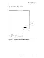
Page 199: ...Hardware Options V 3600 C 3 Figure C 2 shows the jumper location Figure C 2 Jumper Location for Ground Option Signal Labels C H SIG...

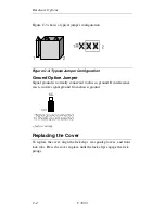
Page 200: ...d Option Jumper Signal ground is normally connected to chassis ground If interference exists isolate signal ground from chassis ground factory setting Replacing the Cover To replace the cover align th...

Page 201: ...cedure Note In some cases the observer must distinguish between rapid LED blinking and steady on in tests Telephone Interface 1 Connect the modem to the dial in line by the LINE jack on the back panel...

Page 202: ...are available 3 When random errors are present the TEST PATTERN ERRORS display counts receive errors 4 If the circuitry is working properly the front panel indicators show the following 5 Configure t...

Page 203: ...mode If the digital bilateral loop is enabled at the remote the remote DTE is looped back to itself 2 An alternative to the above procedure is to request the operator at the remote modem to configure...

Page 204: ......

Page 205: ...Reference Command Page S Reg Description AT 5 3 Attention code command prefix A 5 4 Repeat last command 5 22 S2 S12 Escape sequence pause pause A 5 17 Answer D 5 13 9 4 Dial Dial Modifiers T 5 14 S14...

Page 206: ...g and carrier is present O 5 25 Restore data mode after escape O1 Retrain and restores data mode after escape Q 5 6 S14 Response displays on Q1 S14 Response displays off Q2 S14 Response displays on in...

Page 207: ...5 19 S21 DCD always on C1 S21 DCD on while carrier is present C2 S21 DCD off 5 seconds after disconnect C3 S21 DCD follows remote RTS D 5 20 S21 DTR ignored D1 S21 DTR recalls command mode D2 S21 DTR...

Page 208: ...protocol sync data EBCDIC M9 V 25 bis async dialer SDLC protocol sync data EBCDIC NRZ M10 V 25 bis async dialer SDLC protocol sync data ASCII NRZ1 M11 V 25 bis async dialer sync data EBCDIC NRZ1 P 5...

Page 209: ...clock X2 S27 Receive clock Y 5 38 Powerup with user option set 1 Y1 Powerup with user option set 2 Y Display powerup option set Zn x 5 40 Store dial string x to location n n 0 9 A 6 6 S64 Disable auto...

Page 210: ...E1 S60 Enable auto retrain L 5 29 S81 Disabled minimum DCE speed L1 S81 Disabled L2 S81 1200 bps min L3 S81 2400 bps min L4 S81 4800 bps min L5 S81 9600 bps uncoded min L6 S81 9600 bps min L7 S81 7200...

Page 211: ...20 ms increments n 1 255 default is 35 700 ms C 6 11 S60 Disable auto reliable buffer C1 S60 Buffer data for 4 seconds or 200 characters G 6 8 S54 Disable modem port flow control G1 S54 Enable modem p...

Page 212: ...normal fallback Q 6 7 S54 Disable DTE flow control Q1 S54 Enable DTE XON XOFF flow control Q2 S54 Enable CTS flow control to the DTE Q3 S54 Enables bilateral CTS RTS flow control Q4 S54 Disable DCE f...

Page 213: ...alk mode DA1 Switches modem to data mode DB 5 36 S32 Manual dial backup operation DB1 S32 Automatic dial backup operation DG 7 7 S34 Disables bilateral digital loop DG1 S34 Enables bilateral digital l...

Page 214: ...12 9600 bps RD 7 8 S34 Ignore pin 21 RD1 S34 DTE commanded RDL enabled RO 5 41 S29 Retain options at disconnect RO1 S29 Restore options at disconnect RR 5 31 Rate negotiate to 2400 RR1 Rate negotiate...

Page 215: ...e selection threshold 10 2 BER TLn 5 36 S52 Sets leased line transmit level to n where n is a number between 0 and 30 corresponding to 0 to 30 db H 5 32 Online quick reference H string Online quick re...

Page 216: ...Service Class setting FCLASS Display available Service Class settings FAA 9 10 Enables fax auto answer function FR Fax auto answer DTE autobaud forced to 19200 FR1 Fax auto answer DTE autobaud forced...

Page 217: ...short train 96 V 29 9600 bps 97 V 17 9600 bps 98 V 17 9600 bps with short train 121 V 17 12000 bps 122 V 17 12000 bps with short train 145 V 17 14400 bps 146 V 17 14400 bps with short train FTx 9 9 C...

Page 218: ...Display current security status EH pw 8 7 Enable security pw superuser password F pw pw 8 10 Reinitialize security IBn 8 11 Display user information for a block of up to ten valid users n first user...

Page 219: ...user changes password and callback number W2 Enable remote superuser W Display user changes remote superuser option status 8 11 Local logoff n pw 8 11 8 12 Local logon n user number and pw password S...

Page 220: ...Remote configuration DTE speed 14400 bps RB9 Remote configuration DTE speed 16800 bps RB10 Remote configuration DTE speed 19200 bps RB11 Remote configuration DTE speed 21600 bps RB12 Remote configura...

Page 221: ...W Carrier validation 6 0 6 sec S10 RW Loss carrier delay time 14 1 4 sec S11 RO 10 6 DTMF tone duration 80 ms S12 RW Escape sequence pause 50 1 sec S14 RW 10 8 Bit mapped 8A hex S16 RO 10 9 System tes...

Page 222: ...19 DTE word length parity 18 hex S62 RW Disconnect buffer delay 0 S63 RW Maximum protocol block size 255 S64 RW 10 20 Auto reliable character 0 S67 RO Link speed status 0 S69 RW 10 21 Maximum DCE spee...

Page 223: ...efaults V 3600 E 19 S91 RW 10 27 Current modulation 0 S95 RW V 34 settings f3 hex S96 RW 10 28 V 34 settings a0 hex S97 RW Bit mapped 06 hex S Reg RO RW Page Function Default Factory Set 1 RO Read onl...

Page 224: ...ial stored number command a address DIC 11 7 Disregard incoming call command PRK 11 13 Save current option settings PRLa b 11 8 Link number at address a with number at address b PRNa nn n 11 6 Program...

Page 225: ...ess connection made at 28800 CNX 26400 bps Intermediate call progress connection made at 26400 CNX 24000 bps Intermediate call progress connection made at 24000 CNX 21600 bps Intermediate call progres...

Page 226: ...ber is delayed for xxx minutes INC Incoming ring detected INVCU Invalid command command unknown INVMS Invalid command message syntax error INVPS Invalid command parameter syntax error INVPV Invalid co...

Page 227: ...dial tone Jack type RJ11 Wait delay 2 seconds Line current disconnect long Pause delay 2 seconds Long space disconnect enabled Call timeout 30 seconds V 22 guard tone disabled Answer on 1 ring Autoca...

Page 228: ...ait delay 2 seconds Line current disconnect long Pause delay 2 seconds Long space disconnect enabled Call timeout 30 seconds V 22 guard tone disabled Answer on 1 ring Autocallback disabled PROTOCOL OP...

Page 229: ...RJ11 Wait delay 2 seconds Line current disconnect long Pause delay 2 seconds Long space disconnect disabled Call timeout 30 seconds V 22 guard tone disabled Answer on 1 ring Autocallback disabled PRO...

Page 230: ...Transmit level 0 dBm Pause delay 2 seconds Dial backup manual Call timeout 60 seconds Lookback timer 15 min Answer on 1 ring Jack type RJ11 Autocallback disabled Line current disconnect long Long spa...

Page 231: ...onds Dial backup manual Pause delay 2 seconds Lookback timer 15 min Call timeout 30 seconds Jack type RJ11 Answer on 1 ring Line current disconnect long Autocallback disabled Long space disconnect ena...

Page 232: ...delay 2 seconds Dial backup manual Pause delay 2 seconds Lookback timer 15 min Call timeout 30 seconds Jack type RJ11 Answer on 1 ring Line current disconnect long Autocallback disabled Long space di...

Page 233: ...el 0 dBm Wait delay 2 seconds Dial backup manual Pause delay 2 seconds Lookback timer 15 min Call timeout 30 seconds Jack type RJ11 Answer on 1 ring Line current disconnect long Autocallback disabled...

Page 234: ...vel 0 dBm Wait delay 2 seconds Dial backup manual Pause delay 2 seconds Lookback timer 15 min Call timeout 30 seconds Jack type RJ11 Answer on 1 ring Line current disconnect long Autocallback disabled...

Page 235: ...RJ11 Wait delay 2 seconds Line current disconnect long Pause delay 2 seconds Long space disconnect disabled Call timeout 30 seconds V 22 guard tone disabled Answer on 1 ring Autocallback disabled PRO...

Page 236: ......

Page 237: ...and decimal numbers are as follows Hexadecimal Examples Binary Decimal Hexadecimal 0000 0 0 0001 1 1 0010 2 2 0011 3 3 0100 4 4 0101 5 5 0110 6 6 0111 7 7 1000 8 8 1001 9 9 1010 10 A 1011 11 B 1100 12...

Page 238: ...E ACK 6 06 LC lower case F BEL 7 07 delete G BS 8 08 H HT 9 09 I LF 10 0A SMM J VT 11 0B VT vertical tab K FF 12 0C FF form feed L CR 13 0D CR carriage return M SO 14 0E SO shift out N SI 15 0F SI sh...

Page 239: ...42 2A SM 43 2B C2 CU2 44 2C 45 2D EQ enquiry 46 2E AK acknowledgment 47 2F BL bell 0 48 30 1 49 31 2 50 32 SY sync 3 51 33 4 52 34 PN 5 53 35 6 54 36 UC uppercase 7 55 37 ET end of transmission 8 56...

Page 240: ...77 4D plus N 78 4E O 79 4F ampersand P 80 50 Q 81 51 R 82 52 S 83 53 T 84 54 leading pad U 85 55 V 86 56 W 87 57 X 88 58 Y 89 59 exclamation Z 90 5A dollar sign 91 5B asterisk 92 5C close parenthesis...

Page 241: ...t 116 74 u 117 75 v 118 76 w 119 77 x 120 78 y 121 79 single quote z 122 7A colon 123 7B pound 124 7C at 125 7D apostrophe 126 7E equal DEL 127 7F double quote 128 80 129 81 a 130 82 b 131 83 c 132 8...

Page 242: ...3 l 148 94 m 149 95 n 150 96 o 151 97 p 152 98 q 153 99 r 154 9A 155 9B 156 9C x 157 9D 158 9E 159 9F 160 A0 161 A1 162 A2 s 163 A3 t 164 A4 u 165 A5 v 166 A6 w 167 A7 x 168 A8 y 169 A9 z 170 AA 171 A...

Page 243: ...188 BC 189 BD close bracket 190 BE not equal 191 BF 192 C0 open brace 193 C1 A 194 C2 B 195 C3 C 196 C4 D 197 C5 E 198 C6 F 199 C7 G 200 C8 H 201 C9 I 202 CA 203 CB 204 CC unprintable character 205 CD...

Page 244: ...E1 226 E2 S 227 E3 T 228 E4 U 229 E5 V 230 E6 W 231 E7 X 232 E8 Y 233 E9 Z 234 EA 235 EB 236 EC unprintable character 237 ED 238 EE 239 EF 240 F0 0 241 F1 1 242 F2 2 243 F3 3 244 F4 4 245 F5 5 246 F6...

Page 245: ...CFIRT Call Failure Indication Ringback Detected Ch Gnd Chassis Ground CIC Connect Incoming Call CO Central Office COS Call Originate Status CR Carriage Return CRC Cyclic Redundancy Check CRQ Call Req...

Page 246: ...er Syntax Error INVPV Invalid Command Parameter Value Error I O Input Output IS International Standard K KBD Keyboard kbps Kilobits per Second L LAL Local Analog Loopback LAPD Link Access Protocol D C...

Page 247: ...k RNG Ringback Detection RO Receive Only ROM Read Only Memory RT Remote Terminal RTS RS Request to Send RX Receive S SD Send Data SDLC Synchronous Data Link Control IBM SGND Signal Ground SG SH Switch...

Page 248: ...G 4 V 3600 Abbreviations and Acronyms X X CCITT Recommendation Designation XMIT Transmit XOFF Transmitter Off XON Transmitter On...

Page 249: ...this process once started 1 Activate your data communications software package and set up your DTE for 57 6 kbps 2 Enter AT You should receive an OK response message 3 Enter AT P1 password 8 digits Fo...

Page 250: ...plete The process can take several minutes One of two messages returns DOWNLOAD OK indicates a successful upgrade DOWNLOAD ERROR indicates a problem with the download Enter ATI3 if you want to verify...

Page 251: ...s are pre configured for a country or region of operation These default options vary by country The tables that follow show for countries or regions with changes the default parameter option the avail...

Page 252: ...T Dial Type 0 0 1 AT TD or ATS51 Dial Transmit Tx Level 10 0 15 Dial Wait 8 ATS11 DTMF Tone Length 80 50 255 AT G Guard Tone 0 0 1 2 ATH1 LAL Busy Out Allowed AT TL or ATS52 Leased Line Transmit Tx Le...

Page 253: ...AT TD or ATS51 Dial Transmit Tx Level 15 1 15 Dial Wait 10 ATS11 DTMF Tone Length 80 50 255 AT G Guard Tone 0 0 1 2 ATH1 LAL Busy Out Allowed AT TL or ATS52 Leased Line Transmit Tx Level 1 1 15 ATS8...

Page 254: ...or ATT Dial Type 0 0 1 AT TD or ATS51 Dial Transmit Tx Level 10 0 15 Dial Wait 10 ATS11 DTMF Tone Length 80 50 255 AT G Guard Tone 0 0 1 2 ATH1 LAL Busy Out Allowed AT TL or ATS52 Leased Line Transmit...

Page 255: ...255 ATP or ATT Dial Type 0 0 1 AT TD or ATS51 Dial Transmit Tx Level 9 0 20 Dial Wait 2 ATS11 DTMF Tone Length 72 50 255 AT G Guard Tone 0 0 1 2 ATH1 LAL Busy Out Allowed AT TL or ATS52 Leased Line Tr...

Page 256: ...ATT Dial Type 0 0 1 AT TD or ATS51 Dial Transmit Tx Level 10 9 30 Dial Wait 10 ATS11 DTMF Tone Length 80 50 255 AT G Guard Tone 0 0 1 2 ATH1 LAL Busy Out Allowed AT TL or ATS52 Leased Line Transmit T...

Page 257: ...tributor Questions About Product Shipment or Technical Assistance Please call the nearest Telenetics representative or Customer Administration at 949 455 4000 To Access the Telenetics Internet Web Pag...

Page 258: ......

Page 259: ...ts rented to others This warranty applies only to hardware products manufactured by or for Telenetics and identified by the Telenetics trademark trade name or product identification logo affixed to th...

Page 260: ...TELENETICS LIMITED WARRANTY SERVICE To take advantage of this warranty you must do the following If you are having trouble with your modem contactTelenetics using the appropriate number from the Serv...

Page 261: ...F 1 Async DTR dialer DTR async dialer 10 12 Async sync mode s register settings 10 12 AT command answer 5 17 AT command set disable 5 33 S register enable disabling 10 12 AT command statement 5 3 AT...

Page 262: ...5 25 10 11 L 5 36 10 12 10 14 M 5 25 10 12 10 13 P 5 26 10 11 R 5 21 10 10 10 23 S 5 20 10 10 T 5 43 10 11 V 5 40 W 5 38 X 5 27 10 12 Y 5 38 Z 5 40 CNx n 5 40 DA 5 32 DB 5 36 10 14 DG 10 14 FB 5 22 10...

Page 263: ...5 10 22 O 5 25 10 18 P 10 8 Q 5 6 6 7 10 8 R 5 21 10 19 response commands 5 5 T 6 10 10 8 10 18 V 5 6 10 8 10 19 W 5 6 X 6 8 10 10 10 16 Y 5 25 10 10 Z 5 39 Attention code AT 5 3 Auto reliable data bu...

Page 264: ...transmit frequency A 2 internal transmit frequency A 2 s register settings 10 12 synchronous transmit source of 5 27 Command Index and Defaults E 1 Comments about documentation 1 Compression s regist...

Page 265: ...14 Dial modifiers 5 15 P 5 14 R 5 15 Sn 5 16 Dial tone pulse s register settings 10 8 Dialing Placing a call 3 2 Digital interface specifications A 1 Digital loopback 10 9 Direct mode 6 3 6 9 Disconn...

Page 266: ...to command mode 5 22 F Factory option set loading 5 39 Factory option sets set 1 E 23 Fallback character 6 6 FAULT ISOLATION PROCEDURE D 1 Fax commands class1 quick reference E 12 D 11 5 11 6 11 7 11...

Page 267: ...Leased lines 2 7 Line current disconnect s register settings 10 14 Line equalization A 3 Line type s register settings 10 12 Link layer protocols A 3 Linked Number List 11 10 Local analog loopback DT...

Page 268: ...ecurity local 8 3 Remote 8 2 Option selection methods of 3 1 Option Sets E 23 Options retaining restoring 5 41 Options retained restored 10 12 P Parity s register settings 10 19 Password 8 3 8 6 chang...

Page 269: ...List of Stored Options 11 14 Response messages 5 6 10 8 10 10 Restore Factory Settings 11 13 Returning the modem 12 2 Revision Level 5 31 RI LED ring indicator s register settings 10 19 Ring indicato...

Page 270: ...S register autoanswer 10 5 hexadecimal decimal values 10 2 S register commands Sn v 10 4 Sn v 10 3 Sn v 10 3 Sn 10 3 Sn 10 3 S registers changing values 10 3 individual bit command 10 4 quick referen...

Page 271: ...10 19 S62 10 19 S63 10 19 S64 10 20 S67 10 20 S69 10 21 S7 10 6 S70 10 22 S71 10 22 S72 10 23 S73 10 23 S74 10 23 S75 10 23 S76 10 24 S77 10 24 S78 10 24 S79 10 24 S8 10 6 S80 10 25 S81 10 26 S88 10 2...

Page 272: ...ttings 10 13 V 25 bis response messages E 21 V 25 bis auto dialer commands quick reference E 20 V 25 bis Autodialer 11 7 11 8 11 9 11 10 11 15 V 25 bis autodialer commands quick reference E 21 V 25 NR...

Page 273: ...V 3600 Index 13 Index continued s register settings 10 16 XON XOFF characters from DTE s register settings 10 15...

Reviews: