background image

Selecting and Monitoring Audio

Selecting and Monitoring Audio

The waveform monitor provides several methods to monitor audio signals. You can measure levels, monitor phase, and
display phase correlation. You can specify meter ballistics and scales, set the Test and Peak Program indicator levels, and
specify how phase is displayed.

NOTE.

With audio option DA, the waveform monitor can monitor AES, analog and Embedded audio; Option DG can only

monitor AES and embedded audio.

Selecting the Audio Input

You select the audio input to be monitored from the front-panel AUDIO button pop-up menu.

NOTE.

The Audio display can appear in only one tile at a time.

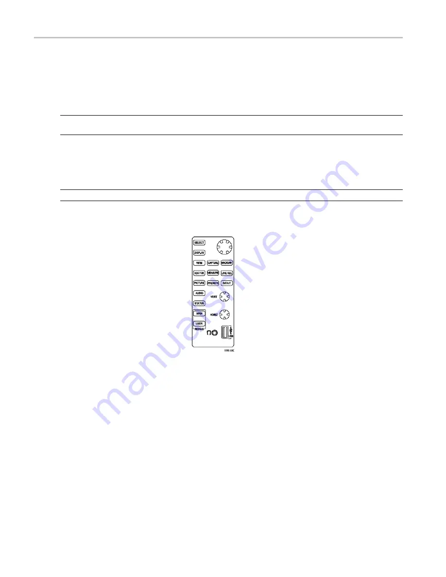
To select the audio input to monitor:

1.

Select a tile.

2.

Press the AUDIO button to open the
Audio display.

114

Quick Start User Manual

Artisan Technology Group - Quality Instrumentation ... Guaranteed | (888) 88-SOURCE | www.artisantg.com

Summary of Contents for WFM6100 Opt. MB

Page 1: ...l service in house repair center WE BUY USED EQUIPMENT Sell your excess underutilized and idle used equipment We also offer credit for buy backs and trade ins www artisantg com WeBuyEquipment REMOTE INSPECTION Remotely inspect equipment before purchasing with our interactive website at www instraview com LOOKING FOR MORE INFORMATION Visit us on the web at www artisantg com for more information on ...

Page 2: ...onitors Quick Start User Manual Test Equipment Depot 800 517 8431 99 Washington Street Melrose MA 02176 FAX 781 665 0780 TestEquipmentDepot com Artisan Technology Group Quality Instrumentation Guaranteed 888 88 SOURCE www artisantg com ...

Page 3: ...urement 25 To Set Display and Measurement Parameters 26 To Select Among Video Inputs 26 To Set Gain Horizontal Magnification and Sweep 28 To Use Presets 30 To Measure Waveforms with Cursors 39 To Capture the Display 40 To Set Line Select Mode 46 To Adjust Headphone Volume and Source 47 To Configure Your Instrument 48 To Use Online Help 49 To Connect to a Network 51 To Connect Directly to a PC 54 T...

Page 4: ...hecks 105 Checking RGB Gamut 107 Checking Composite Gamut 109 Checking Luma Gamut 110 Automating Gamut Checks 111 Adjusting Gamut Limits 112 Selecting and Monitoring Audio 114 Selecting the Audio Input 114 Checking Audio Level Phase 116 Checking Surround Sound 118 Remote Communications 124 Using the Remote Web Interface 124 Using the Remote Application 125 To Upgrade the Waveform Monitor Software ...

Page 5: ...he Product This product is grounded through the grounding conductor of the power cord To avoid electric shock the grounding conductor must be connected to earth ground Before making connections to the input or output terminals of the product ensure that the product is properly grounded Observe All Terminal Ratings To avoid fire or shock hazard observe all ratings and markings on the product Consul...

Page 6: ... and Terms on the Product These terms may appear on the product DANGER indicates an injury hazard immediately accessible as you read the marking WARNING indicates an injury hazard not immediately accessible as you read the marking CAUTION indicates a hazard to property including the product The following symbols may appear on the product iv Quick Start User Manual Artisan Technology Group Quality ...

Page 7: ...ymbol shown below indicates that this product complies with the European Union s requirements according to Directive 2002 96 EC on waste electrical and electronic equipment WEEE For information about recycling options check the Support Service section of the Tektronix Web site www tektronix com Mercury Notification This product uses an LCD backlight lamp that contains mercury Disposal may be regul...

Page 8: ...lity waveform processing CaptureVu capability that can capture a full frame of video data either user initiated or triggered by an alarm condition MyMenu capability that lets you create custom menus that simplify instrument operation Available measurement options that offer industry leading capability for SDI signal measurement and video data analysis Available audio options that offer industry le...

Page 9: ...e port for quickly verifying sound quality Simple touch screen controls let you quickly check the stereo pairs shown on the audio bar display Network access and control through a simple Web page interface a more complete Java based remote control interface or by SNMP Ground closure remote control port with an alarm output and support for recalling instrument presets Support for printing the displa...

Page 10: ... Specifications Procedure for checking performance and list of specifications WVR WFM Series Programmer Manual Programmers command reference for controlling the instrument WFM6100 WFM7000 WFM7100 Series Waveform Monitors Service Manual Optional manual supporting module level servicing of the instrument Conventions Used in this Manual The following icons are used throughout this manual Sequence Ste...

Page 11: ...ification Technical Reference Tektronix part number 071 1897 00 Power Cords The WFM6100 WFM7000 WFM7100 Waveform Monitors are shipped with one of the following power cord options Power cords for use in North America are UL listed and CSA certified Cords for use in areas other than North America are approved by at least one authority acceptable in the country to which the product is shipped Interna...

Page 12: ...monitoring embedded and AES EBU inputs DD Adds support for Dolby Digital AC 3 decode Digital Audio embedded and AES EBU inputs and for Analog Audio Monitoring DDE Adds support for Dolby E decode Dolby Digital AC 3 decode Digital Audio embedded and AES EBU inputs and for Analog Audio Monitoring Supports digital audio formats with up to eight channels Eye Jitter and Data Analysis Options Description...

Page 13: ...e Patterns in 3 Eye 10 Eye SD or 20 Eye HD modes cable length measurements including source signal level and cable loss and Jitter readout PHY Includes the capabilities of Eye option plus advanced physical layer measurements jitter waveform and automated eye measurements DAT Adds data analysis capabilities Allows for logic level view of video and audio digital data stream and ANC data extraction T...

Page 14: ...s blocked and the instrument does not shut down the instrument could be seriously damaged Connecting Power and Powering On Off The waveform monitor operates from a single phase power source with the neutral conductor at or near earth ground The line conductor is fused for over current protection A protective ground connection through the grounding conductor in the power cord is essential for safe ...

Page 15: ...incoming serial signal into one of the waveform monitor SDI inputs NOTE See the Specifications on the Documents CD for maximum allowed cable lengths Option Eye Phy Option SD HD Quick Start User Manual 5 Artisan Technology Group Quality Instrumentation Guaranteed 888 88 SOURCE www artisantg com ...

Page 16: ...tination receiver sets the system return loss In cases where the waveform monitor is placed at the end of a link a BNC termination must be installed on one side of the loop through analog or reference connector The termination must be 75 Ω and DC coupled good return loss extends to DC An appropriate termination would be Tektronix part number 011 0102 00 It is a 75 Ω End of Line termination Compati...

Page 17: ...he tile that is currently being controlled is considered the active tile and it is indicated on the display by a light blue outline around the tile The waveform monitor can also display one tile at a time For example you might want to display just an Eye diagram to view the rise time measurement To select a display to be shown in full screen mode press the DISPLAY button and select the icon that r...

Page 18: ...Two displays that cannot appear in more than one tile at a time are the Audio and DataList displays They can be displayed in only one tile at a time You can display four waveform displays at the same time with each waveform display configured differently 8 Quick Start User Manual Artisan Technology Group Quality Instrumentation Guaranteed 888 88 SOURCE www artisantg com ...

Page 19: ...ays change values using the large knob or change the horizontal and vertical position of a waveform Many values can be set from the display by selecting a touchable readout in the display For example you can change the position of a cursor by touching the cursor readout and changing its position using the large knob Virtually every display has its own menu The display menu is used to change select...

Page 20: ...t for each tile NOTE Only one tile can contain an Audio display or DataList display and only one tile can have the Line Select mode enabled Perform the following steps to configure the display View All Available Measurements Using the Main Menu Press the front panel MAIN button to open the Main menu and display a pop up menu showing all available measurements Note that this pop up menu is the only...

Page 21: ...play mode press the DISPLAY button This displays the Views menu at the bottom of the screen Each tile is represented by a icon soft key in the menu 2 To display a tile full screen touch the icon that represents the tile you want displayed in full screen mode In a full display the displayed tile is always selected 3 To return to four tile view press the Display button and select the 4 Views icon NO...

Page 22: ...tus display shown in the active tile and displays a menu allowing you to change the selected tile to display a status screen a session display or the error log MAIN Displays the Main menu and Main pop up menu providing access to primary and secondary menus Some displays are selectable only in the pop up menu USER Displays a user defined menu CAPTURE Displays menu that enables screen capture of liv...

Page 23: ...y Areas of the Display Three major areas make up the display They are the Status Bar area the Main Display area and the Menu area The Main Display area is where the waveform monitor displays measurement results signal traces and status information The Status Bar appears at the top of the display The Status Bar provides a number of text and icon elements to give you an easily viewed guide to the st...

Page 24: ...lect a single item from a related group of choices For example in the Mag Gain menu Option menu keys are used to select the amount of vertical gain Knob value Menu Keys connect the value to the knob enabling the value to be changed by turning the knob For example in the Closed Caption submenu you can specify the line used for Closed Captioning by selecting the VBI CC Line soft key and turning the ...

Page 25: ...ne line area that is visible if Composite Gamut Arrowhead errors are present 4 Luma Gamut Errors A one line area that is visible if Luma errors are present 5 Alarm Error Indicator An icon that is visible when alarms of types other than those in the four readouts just listed occur 6 Show Menu Hide Menu Touching this soft key causes the menu at the bottom of the display to appear or disappear 7 Onli...

Page 26: ...located along the bottom right portion of the rear panel An instrument with an Eye or Phy option has the SDI inputs arranged vertically Options SD HD Options Eye Phy 16 Quick Start User Manual Test Equipment Depot 800 517 8431 99 Washington Street Melrose MA 02176 FAX 781 665 0780 TestEquipmentDepot com Artisan Technology Group Quality Instrumentation Guaranteed 888 88 SOURCE www artisantg com ...

Page 27: ...ground such as phase to phase in multiphase systems are not recommended as power sources NOTE Only the line conductor is fused for over current protection The fuse is internal Video Input Connectors SDI inputs are active inputs Reference and Composite inputs are passive inputs compensated for 75 Ω 1 Ref Loop A synchronization input The input signal can be analog black burst analog composite video ...

Page 28: ...rence Signals The following tables indicate the supported combinations of input format and reference format An X indicates a tested combination Other combinations of input signal and reference signal within each table may work but are not warranted Operation with an input from one table and a reference from another is not supported for example a 1080i 50 input will not work with 1080i 60 reference...

Page 29: ... x x x x x 1080p 23 98 Hz 3 x x x x x 1080sf 23 98 Hz3 x x x x x 1080p 29 97 Hz 3 x x x 1080sf 29 97 Hz3 x x x 1035i 59 94 Hz 3 x x x 1080i 59 94 Hz 3 x x x 1 Available with Opt CPS 2 Available with WFM7100 Opt SD or with WFM6100 Opt SD 3 Available with WFM7000 and WFM7100 Opt HD only Reference Formats Input Format 720p 24 720p 30 720p 60 1080p 24 1080sf 24 1080p 30 1080sf 30 1080i 60 720p 24 Hz 1...

Page 30: ...ut Power may result in damage to the instrument Option AD Pin Description 1 ANALOG_INPUT_A1_P Balanced differential analog audio input Ch 1 line A positive 2 ANALOG_INPUT_B1_P Balanced differential analog audio input Ch 1 line B positive 3 ANALOG_INPUT_A2_P Balanced differential analog audio input Ch 2 line A positive 4 ANALOG_INPUT_B2_P Balanced differential analog audio input Ch 2 line B positiv...

Page 31: ...ative 26 ANALOG_INPUT_A3_N Balanced differential analog audio input Ch 3 line A negative 27 ANALOG_INPUT_B3_N Balanced differential analog audio input Ch 3 line B negative 28 ANALOG_INPUT_A4_N Balanced differential analog audio input Ch 4 line A negative 29 ANALOG_INPUT_B4_N Balanced differential analog audio input Ch 4 line B negative 30 ANALOG_INPUT_A5_N Balanced differential analog audio input ...

Page 32: ...lanced mode Units that have both analog and digital capability can have AES or embedded inputs converted to analog and then routed to the six balanced outputs Embedded audio can be output to the AES B connector when it is configured as an output AES A can also be routed to the AES B connector Decoded Dolby can also be routed to the analog output connector EXT DISPLAY Connector Pin Assignment This ...

Page 33: ...and indicating to external equipment when alarms have occurred The input of LTC is through the REMOTE connector The REMOTE connector is a 15 pin D type connector with socket contacts Pin Pin name 1 Ground 2 Time Code Positive IN 3 Time Code Negative IN 4 Ground 5 Ground Close Output Has weak pull up with a diode to 5 V so you can get logic swing without pull up OUT 6 Preset Recall 1 Grounding this...

Page 34: ...nnector The waveform monitor provides a 10 100 BaseT Ethernet interface The Ethernet connector is a standard RJ 45 connector 24 Quick Start User Manual Artisan Technology Group Quality Instrumentation Guaranteed 888 88 SOURCE www artisantg com ...

Page 35: ... up menu 4 Repeat steps 1 through 3 until you have selected measurement displays for all tiles that you want to define 5 To display the same measurements in more than one tile select each tile in sequence and then choose the same measurement for each one The display at right shows the display with WFM selected for three tiles with different sweep settings NOTE The Audio and DataList displays can b...

Page 36: ...ake selections from a submenu Some settings provide multiple choices within the submenu For example when selecting the components that are shown in the WFM display you choose from all the available components within one submenu NOTE The selections in a submenu can change depending on settings To Select Among Video Inputs You can connect serial digital component signals and select them for display ...

Page 37: ...For the composite inputs terminate the loop through input properly at the rear panel for any inputs that are not routed to another device Option CPS 4 Press the IN OUT button to display the In Out menu 5 Press the soft key for the input you want to display Quick Start User Manual 27 Artisan Technology Group Quality Instrumentation Guaranteed 888 88 SOURCE www artisantg com ...

Page 38: ... apply to all display types To set Gain 1 Select the tile whose gain you want to adjust This will restore the menu for the tile if it is not currently displayed 2 Push the MAG GAIN button If MAG GAIN is not available for the tile you have selected a message is displayed to let you know that MAG GAIN is not available 3 To set a fixed gain touch the V Gain readout and use the large knob to change th...

Page 39: ...ag readout and use the large knob to change the magnification You can also touch one of the Fixed Mag soft keys 5 Select Mag Best View to optimize the magnification to show the blanking interval for two line and two field displays Line the blanking up on the center graticule and then press Mag Best View to expand NOTE You can also change the V Gain and H Mag values by touching the readouts and usi...

Page 40: ...Jitter displays the choices available are are 1 Line 2 Lines 1 Field and 2 Fields To Use Presets A Preset is a saved version of the instrument settings in a particular configuration Using Presets saves you time because you only need to press a couple of buttons to change a range of instrument settings to meet a specific measurement need Presets are created and recalled using the PRESETS button on ...

Page 41: ... select Yes to create a descriptive 11 character name for the Preset or select No to save the preset using the default label such as A2 The setup will be stored for later recall To Recall an Existing Preset 1 Push the PRESETS button 2 Touch one of the soft keys in the Presets menu Unless you have renamed them they will be labeled A1 A5 Quick Start User Manual 31 Artisan Technology Group Quality In...

Page 42: ...will switch to the saved preset corresponding to the soft key pressed To Copy a Preset to or from a USB Flash Drive 1 Insert a flash drive into the USB port on the front panel 2 Touch the PRESETS button 3 Touch the Settings soft key 4 Touch the Copy Preset s soft key 32 Quick Start User Manual Artisan Technology Group Quality Instrumentation Guaranteed 888 88 SOURCE www artisantg com ...

Page 43: ...drive to the instrument touch the source location if more than source is listed Then touch the Preset in the Source Presets list that you want to copy to the instrument Once you touch a Preset label the Source Location and Source Presets labels will change to Destination Location and Destination Presets 9 Select a destination location from the list either Internal or USB depending on the direction...

Page 44: ... menu touch the USB Unmount soft key and them remove the USB flash drive from the instrument To Recall the Factory Preset 1 Push the PRESET button 2 Touch the Settings soft key to display the submenu 3 From the Settings submenu touch the Recall Preset soft key 4 From the menu in the center of the display touch the Factory soft key 34 Quick Start User Manual Artisan Technology Group Quality Instrum...

Page 45: ...nter of the display choose any available preset for the instrument to use at power up NOTE The Latest preset is the instrument setup at the time the instrument was last shutdown using the Shutdown command MAIN Standby Shutdown It is not the instrument setup the last time power was removed from the instrument Quick Start User Manual 35 Artisan Technology Group Quality Instrumentation Guaranteed 888...

Page 46: ...ngs soft key to display the submenu 3 From the Settings submenu touch the Rename Preset s soft key 4 From the menu in the center of the display choose the Source location if necessary 36 Quick Start User Manual Artisan Technology Group Quality Instrumentation Guaranteed 888 88 SOURCE www artisantg com ...

Page 47: ...he Keyboard soft key and type in a new name for the selected preset or group Press Return to save the new name NOTE Preset names are limited to 11 characters Group names cannot exceed 8 characters Quick Start User Manual 37 Artisan Technology Group Quality Instrumentation Guaranteed 888 88 SOURCE www artisantg com ...

Page 48: ...7 Press the Rename soft key to apply the new name 8 Press the Exit soft key when you are finished renaming presets 38 Quick Start User Manual Artisan Technology Group Quality Instrumentation Guaranteed 888 88 SOURCE www artisantg com ...

Page 49: ... Touch the Cursors soft key to display the Cursors submenu 3 To display cursors touch the soft key for the type of cursors you want displayed so that the box is checked 4 Touch Track Independent to specify how cursor pairs move with respect to each other Select Track if you want both cursors V1 V2 or T1 T2 to move together as a single unit Select Independent to move each cursor by itself Quick Sta...

Page 50: ...and cursor 2 To Capture the Display Use the Capture function to capture the current image for traces waveform gamut displays and vector if selected Capture is useful for comparing sources or for capturing transient events The frozen image is shown in a different color to distinguish it from the live image Use Capture Trace Capture Buffer to freeze a display you want to keep or show to someone else...

Page 51: ...res made using this method do not include the associated decoded data To capture a display 1 Press the front panel CAPTURE button This displays the Capture menu 2 Press the Settings soft key 3 Touch the Buffer Trace soft key to set the type of Capture Touch Close Settings to remove the submenu 4 To display the capture be sure the Capture Display On soft key is checked NOTE The Live Display On sett...

Page 52: ...played another capture cannot be made until the current capture is cleared Triggering a Capture Based on Error Events You can set up the waveform monitor to initiate a Capture when certain errors occur This triggered Capture mode requires that the capture type be set to Buffer To initiate a capture based on an error event 1 Select the tile you want to capture 2 Press the CAPTURE button This displa...

Page 53: ...h OK to save your selections 7 Touch Close Settings to remove the submenu 8 To initiate the trigger capture process touch the Run Stop soft key The waveform monitor will perform a buffer capture when one of the selected trigger events occurs Clearing the Capture Buffer 1 Press the CAPTURE button to display the Capture menu 2 Touch the Clear soft key Quick Start User Manual 43 Artisan Technology Gr...

Page 54: ...he USB flash drive is recognized a description of the drive will appear after USB Storage Device If it is not recognized touch the Reset soft key to mount the flash drive If the flash drive is still not recognized the flash drive may not be compatible try using another flash drive 6 Touch the Keyboard soft key to display a keyboard you can use to enter a name for the file 7 Enter a name for the fi...

Page 55: ...trument Restoring a Buffer Capture from a USB Flash Drive 1 Insert a flash drive into the USB port on the front panel 2 Touch the CAPTURE button to display the Capture menu 3 Touch the Settings soft key to display the submenu 4 If the USB Flash Drive is not recognized a description of the drive will appear after USB Storage Device touch the Reset soft key to mount the flash drive If the flash driv...

Page 56: ...menu is not visible pressing the LINE SEL button will display the menu it will not turn off Line Select mode 3 Press the appropriate soft key to select the appropriate field The selections available depend on input signal standard and format 4 Turn the GENERAL knob to select the line you want to view NOTE If other Waveform display tiles are in Field Sweep or Picture mode the selected line will be ...

Page 57: ...g your hearing before you put on headphones always turn the volume down to the minimum and then turn it up slowly 3 Adjust the headphone volume using the large knob The color of the headphone bar changes to give an indication of the volume level 4 To change which meter bars are used as the source for the headphones touch either meter bar in a pair to select that pair as the source 5 Touch the head...

Page 58: ... the touch screen For details on how to run the diagnostic and calibration procedures see the service manual Colors Intensity Set colors for trace and graticule and set intensity for elements of the display Readouts Brightups Enable the display of brightups on gamut errors enable the display of the line select cursor on the Picture display specify whether Capture applies to all tiles or the select...

Page 59: ...e help is enabled selecting any soft key on the display will display a help topic To makes changes to instrument settings you must turn off the context sensitive help To display online help 1 Display the menu or submenu for which you want to view the online help 2 Press the in the Status Bar When Help mode is enabled the icon changes color to green If the Help mode is not enabled the icon is white...

Page 60: ...h the Help soft key to enable Help mode 2 Touch any soft key to get help on that soft key 3 Use the navigation keys at the bottom of the help window to scroll through the help text 4 Touch Close to close the Help window 5 Touch the Press any button to get context sensitive help soft key to disable Help mode 50 Quick Start User Manual Artisan Technology Group Quality Instrumentation Guaranteed 888 ...

Page 61: ...for the instrument To get an address talk to your LAN administrator Set up the monitor as described in the steps that follow NOTE You may want to connect directly between your PC and the WFM7100 See page 54 To Connect Directly to a PC 1 Press the MAIN button to display the Main menu 2 Touch the Config soft key to display the Configuration submenu 3 Touch the Utilities soft key 4 Touch the Communic...

Page 62: ...der Remote Web Interface 8 If you can t use DHCP you will have to set the IP Address subnet mask and gateway address network parameters in the Network Setup menu see your LAN administrator for the required values Be sure to use compatible addresses between the PC and the monitor 9 If you will use SNMP commands with the waveform monitor touch the SNMP Setup soft key 52 Quick Start User Manual Artis...

Page 63: ...ng the waveform monitor will strip any leading or trailing spaces in the string for example my stuff will become my stuff The private community string cannot be blank If you input a blank string the instrument will set it to the default string Trap Destination 1 4 Address These settings allow you to set IP addresses to which SNMP traps are sent Remote SNMP Mode This setting enables you to allow or...

Page 64: ...nual IP mode and set the IP address manually Be sure to set an address that is compatible with the setting of your PC 3 Configure the SNMP setup if used See page 51 To Connect to a Network To Print Screens and Event Logs The waveform monitor can print screens and event logs to printers connected by a USB cable 1 Connect your printer to the USB port on the front panel 2 If you want to print a scree...

Page 65: ...uired 7 If you are printing an error log you may want to limit the number of pages printed error logs can be long Select the Page Limit soft key and chose a page limit 8 Touch Select Printer and chose which printer you will use See the following procedure Creating a Printer for instructions on how to add a printer to the list Quick Start User Manual 55 Artisan Technology Group Quality Instrumentat...

Page 66: ...e a printer for the Select Printer dialog To create a printer 1 Press the MAIN button to display the Main menu 2 Touch the Print soft key to display the Print submenu 3 Touch Select Printer to display the Select Printer dialog box 56 Quick Start User Manual Artisan Technology Group Quality Instrumentation Guaranteed 888 88 SOURCE www artisantg com ...

Page 67: ... an appropriate printer 6 Select a USB Device identifier Use different identifiers for different printers 7 Touch the Keyboard soft keys to enter a name for the new printer and then touch Return 8 Touch OK to save the configuration Quick Start User Manual 57 Artisan Technology Group Quality Instrumentation Guaranteed 888 88 SOURCE www artisantg com ...

Page 68: ...the MAIN button to enter the Main menu 2 Select Configure User Menu 3 Select Conf User On from the menu A check mark will appear in the check box when the function is enabled 4 Touch OK to begin configuring your custom menu NOTE The menu configuration process will display a series of instructions to guide you through the process of creating your menu 58 Quick Start User Manual Artisan Technology G...

Page 69: ... will be added to your User menu For example if you wanted to add the Diamond display to your User menu since it is not available from the front panel you would touch the Diamond soft key If the soft key you want to add to your User menu is not currently visible you must navigate to the menu where the soft key is located and then touch the icon to add the soft key to the User menu Quick Start User...

Page 70: ...played 7 To exit the Configure User menu mode select Configure User Menu from the Main menu and clear Conf User On 8 To display your custom menu press CUSTOM on the front panel 9 Once you have completed your User menu save it in a Preset CAUTION User menus are saved as part of a Preset Therefore if you recall a Preset your existing User menu will be overwritten by the recalled Preset Even if the r...

Page 71: ...User menu by using the Remove 1 User Button soft key in the Configure User Menu submenu You can remove all buttons from the User menu by using the Remove 1 User Button soft key in the Configure User Menu submenu Waveform Display The WFM button displays the Waveform WFM display which is the familiar voltage versus time display used to view a waveform You can view the input signal in line or field s...

Page 72: ...other The Waveform menu Filter selection allows you to select filters to be applied to SDI video signals This is useful to isolate a specific characteristic of the input For example to measure amplitude you may want to use a Low pass filter to remove the high frequency components To choose a filter select one of the following filters from the Filter menu Flat Display with the full available bandwi...

Page 73: ...he Gain setting Display Elements for Composite Inputs 1 Line When LINE SEL is enabled touch the readout to select and use the knob to select line being viewed 2 Gain x1 00 Touch to select and use the knob to adjust the Gain setting 3 Phase Touch to select and use the knob to adjust the Phase setting NOTE You can toggle between adjusting the Phase and Gain by pressing the SELECT button Quick Start ...

Page 74: ...nly on Vector displays with PAL input format The Phase Normal mode shows both phases of the vector that results from the phase alternating on lines PAL The Phase mode inverts the phase on every other line to undo the PAL sequence and thus shows all lines in one phase orientation Bar Target Setting The bar target setting either 75 or 100 Picture Display Pressing the PICTURE button calls up the Pict...

Page 75: ...site signals Audio Display Pressing the AUDIO button brings up the Audio Display The Audio display provides level meters and a phase or surround display for monitoring audio signals The Audio display always shows the level meters and correlation meters When you choose to display the Aux Display you can choose to display a Phase display also known as Lissajous or a Surround display The left portion...

Page 76: ...plays phase correlation between the two channels of each appropriate pair Located under the bars for the same channels Duplicated under the Phase display Has configuration response time Test level and Peak program level indicators Diamond shaped markers between the level bars that indicate the configurable limits set up for the display Above the Test level the bar displays in a yellow color Above ...

Page 77: ...EO input is unrecognizable AES PARITY The incoming subframe does not have even parity as specified by the digital audio standards The data sample is unreliable and is ignored The level meters and Lissajous display treat the sample as a zero sample AES CRC ERROR The CRC code in the AES channel status packet is incorrect Sometimes the CRC code is set to zero indicating that the signal is missing whe...

Page 78: ... of audio to video The Audio menu also provides two pictorial displays that allow you to monitor the signal Audio phase displays include phase correlation meters a flexible Lissajous display for any pair of channels and a multiple channel Surround Sound display that shows audio levels weighted or un weighted total sound volume phantom source locations and the dominant sound position To add a phase...

Page 79: ...splay is created by plotting luminance versus B Y in the upper half of the display and inverted luminance versus R Y in the lower half of the display The bright dot in the center of the screen is the luminance blanking level The points above and below this show the plots of the different color components based on their signal amplitude The Lightning display requires a color bar test signal be used...

Page 80: ...that can be outside the current gamut limits yet not be reported as a gamut error 4 Threshold indicators indicates the threshold settings using blue dashed lines NOTE To change the threshold settings touch the threshold readouts and then adjust their values using the large knob If the signal appears outside the boundary shown by the blue dashed lines then the signal is violating the limits that ar...

Page 81: ... Y Area setting 2 Y Low threshold Shows the level below which the Luminance value is considered too small and out of gamut Signals below this level will trigger an error alarm if the number of pixels in error exceeds the Y Area setting 3 Y Area Specifies the percentage of the total image pixels up to 10 that can be outside the current Luma limits yet not be reported as an error 4 Y C High threshol...

Page 82: ...ay that simplifies measuring the timing difference between two signals Display Elements 1 Input Signal Indicator A single 1 circle representing timing of input signal relative to the reference 2 Reference Indicator A cross hair indictor centered in the display represents the reference signal 3 Vertical Offset The timing difference between the reference and input signal 4 Horizontal Offset The timi...

Page 83: ...g offset will be shown as zero when the two signals are timed down at the rear of the waveform monitor Rel to Saved Offset which means that the timing will be shown as zero offset when the input signal matches the timing of the signal that was present when the offset was saved using the Save Offset menu entry This selection changes both the numeric readouts and the target in the middle of the timi...

Page 84: ...ts a possible timing offset measurement relative to the reference cross hair Display emphasis is given the circle that times closest to zero offset and the numerical readouts track this pair Nondeterministic cases include timing of slow rate inputs against fast frame rate references or when timing video against film rates 74 Quick Start User Manual Artisan Technology Group Quality Instrumentation ...

Page 85: ... an SD Bowtie test signal with 20 ns time marks which aid in signal evaluation The signal is a 500 kHz sine wave on CH 1 luminance and 502 kHz sine waves on CH 2 Pb and CH 3 Pr For HD the TG2000 can produce an test signal with 1 ns markers The signal is a 2 5 MHz sine wave on CH 1 luminance and 2 502 MHz sine waves on CH 2 Pb and CH 3 Pr Elements of the Bowtie display 1 V Gain The vertical gain To...

Page 86: ...s appear twice as long Use the Select Channels soft key to turn off individual components of the display Data Mode SD Shows the data in the same sequence as it occurs in the serial domain You see a sample of Y then of Cb then of Y Y prime and then of Cr Then the sequence repeats The Y sample is the co sited sample and the Y sample is the isolated luma sample Data Mode HD Splits the serial data int...

Page 87: ...the display is updated at approximately two second intervals rapid data changes cannot be detected Use the large knob and the Select button to enter the DID and or SDID values for the type of ancillary data packet to be monitored You can also touch the readouts on the screen to select either DID or SDID for control using the large knob DID and SDID values have the following characteristics DID and...

Page 88: ...tile and displays the Status menu Status Display Types Alarm Status Shows the status of all alarms the instrument is set to monitor The status of an alarm is displayed in different colors Gray The alarm is not enabled for reporting Red The alarm is occurring now Yellow The alarm is not occurring now but has occurred within the last five seconds Green The alarm is not occurring and has not occurred...

Page 89: ...ata present CC Services When closed caption data is detected the closed caption service s being used are listed Ancillary Data Present Present is displayed when ancillary data is detected None is displayed when there is no ancillary data present Transmission Signal Identifier Indicates whether the TSID is present in the SDI stream If missing Absent will display otherwise the TSID is displayed as a...

Page 90: ...Dolby Status Option DDE display shown with Dolby D source Dolby Status Option DD display shown with Dolby D source 80 Quick Start User Manual Artisan Technology Group Quality Instrumentation Guaranteed 888 88 SOURCE www artisantg com ...

Page 91: ...cs are controlled by the Run Stop and Reset soft keys Error Log Shows error over time For errors to appear Alarms must be enabled for logging in the Main Config Alarm Setup menu The soft keys in the menu are used to navigate through the log The error log is limited to 10 000 entries Quick Start User Manual 81 Artisan Technology Group Quality Instrumentation Guaranteed 888 88 SOURCE www artisantg c...

Page 92: ...on the options you have purchased the waveform monitor supports checking verification and monitoring of the physical layer of SDI signals connected to its SDI inputs in the following ways Option EYE If present the Eye option adds support for eye pattern monitoring of the physical layer of video signals The Eye display includes readouts for P P jitter cable length and cable loss and source level Op...

Page 93: ...s from the Settings menu to display these values Option Eye has includes some of these limits Option Phy includes additional limits 3 V Gain H Mag Adjust the vertical gain and horizontal magnification with these touchable readouts 4 Eye parameter measurements Option Phy adds on screen display of eye and jitter measurements Option Eye has includes some of these measurements Option Phy includes addi...

Page 94: ...be set to display measurements and limits 1 Jitter gauge Augment the jitter readouts with an easy to read visual indicator 2 Limits Touch any limit readout and use the knob to adjust the limit Select Show Limits from the Settings menu to display these values 3 V Gain H Mag Adjust the vertical gain and horizontal magnification with these labels 4 Eye and Jitter measurements Select Show Measure from...

Page 95: ...wo tiles use clock recovery circuit one and the lower two tiles use clock recovery circuit two This means that any combination of Eye and Jitter displays in the top two tiles will have the same bandwidth but any combination of eye and jitter in the left or right two tiles can have any two bandwidths from the list of possible choices Elements of the SDI Status Display 1 Jitter1 and Jitter2 thermome...

Page 96: ...imits Jitter Display On this display you can view additional time domain information such as that listed below that is useful in separating sources of jitter whether they are within a single circuit on a circuit board or from various pieces of equipment in a system Jitter components that are synchronous or nearly synchronous to video line or frame These appear as stationary or near stationary arti...

Page 97: ... soft key See page 86 Displaying the Eye Measurement Menu 2 Touch the Cable Type soft key 3 Select the best match for the type of cable connecting the SDI signal you are measuring 4 Touch the Close Cable Type and Close Settings soft keys Quick Start User Manual 87 Artisan Technology Group Quality Instrumentation Guaranteed 888 88 SOURCE www artisantg com ...

Page 98: ...he following Eye The Eye display shows the SDI input signal directly Equalized Eye The Eye display shows the SDI input signal after it has passed through the internal cable equalizer and comparator 3 Touch the Close Eye Type soft key Setting the Jitter High Pass Filter 1 Touch the Jitter HPF soft key and select a high pass filter value See page 86 Displaying the Eye Measurement Menu NOTE Timing se...

Page 99: ... soft key in the Settings submenu to enable displaying of the limit values Which threshold limits are displayed depends on the installed options 4 Touch the limit value to set and use the general purpose knob to change the value NOTE You can use the SELECT front panel button to sequentially step through and select the threshold limit values 5 Touch the Close Settings soft key Setting the Equalizer...

Page 100: ...ion with typical cable lengths and reduces jitter due to cable effects Use this setting for most signals CAUTION If the equalizer is left in bypass mode the waveform monitor will not work with cables more than a few meters long This applies to all SDI displays 3 Touch the Close Settings soft key To Configure Physical Layer Alarms 1 Press the Main front panel button 2 Touch the Config soft key 3 To...

Page 101: ...m Setup soft key 6 To set individual limit alarms for specific error conditions touch the soft key for the appropriate measurement category The instrument displays the available error conditions that can trigger an alarm and the alarm notification types 7 Select the alarm notification types for one or more error conditions 8 Touch the Save and Close soft key to save the alarm settings and return t...

Page 102: ...matic eye measurements NOTE If you use the measurement cursors to measure the eye waveform you may measure a different result than that shown in the automatic eye measurements readout This is because the automatic amplitude measurement uses histograms in order to be minimally affected by overshoot ringing and noise on the signal Similarly the automatic rise time and fall time measurements use hist...

Page 103: ...r falling edges 7 The cursor Delta readout displays the amplitude of the eye waveform NOTE Signal source amplitudes outside of 10 of 800 mV p p can degrade receiver performance To Manually Measure Aberrations 1 Perform the initial setup for Eye measurements See page 92 To Set Up for Eye Measurements 2 Touch the Cursors soft key The instrument displays the cursors submenu 3 Select the Show Volt sof...

Page 104: ...ursor Delta readout displays the amplitude of the aberration 7 Perform the same voltage cursor measurement on the bottom line thickness including any undershoot and ringing NOTE Aberrations at the top or bottom line of the waveform should not exceed 10 of the signal amplitude Automatic equalizer circuits in receivers may be sensitive to larger aberrations To Manually Measure Rise Time Using Variab...

Page 105: ...lect the Show Timing soft key to enable display of the voltage cursors Timing cursor T1 is selected by default 9 Use the general purpose knob to position timing cursor T1 at the crossing of the rising edge of the Eye waveform and the graticule line two divisions above the bottom of the waveform 10 Select timing cursor T2 11 Use the general purpose knob to position the timing cursor T2 at the cross...

Page 106: ...o display the Settings submenu 4 Touch the Show Measure soft key The measurements are displayed on the left side of the screen NOTE If you use the measurement cursors to measure the eye waveform you may measure a different result than that shown in the automatic eye measurements readout This is because the automatic amplitude measurement uses histograms in order to be minimally affected by oversho...

Page 107: ...circle will be centered on the cross hair The timing offset is also shown numerically as lines and microseconds of advance or delay in the boxes at the right side of the display For input and reference signals with closely related frame rates there is only one timing relationship so a single circle is shown on the display to indicate the timing offset of the input signal For input and reference co...

Page 108: ... Versus Complex Timing 8 Repeat step 6 or 7 for any other signals NOTE As you adjust timing the circle representing the input timing may jump occasionally This is because the color frame detection circuit can be temporarily disrupted as the signal shifts The jump is often a multiple of the field time The circle will settle back to the correct location in a second or so Usage Notes The resolution o...

Page 109: ...he Relative to function to set the offset between a master and a reference signals as the zero point reference for time down applications The Relative to box indicates the chosen zero point for the timing display Rear Panel In this mode default the offset is zero when the measured signal input and reference are at the same timing at the reference at the instrument rear panel This setting was used ...

Page 110: ...om the pop up menu 4 Touch Save Offset from the Timing menu 5 Touch the Rel to Saved Offset soft key 1 The timing of the first input the master signal is at the center of the screen 100 Quick Start User Manual Artisan Technology Group Quality Instrumentation Guaranteed 888 88 SOURCE www artisantg com ...

Page 111: ...g on the Timing display and change from internal to external reference the displayed waveform will not shift position When timing analog composite signals first use the Timing display to get within one clock cycle then adjust system phase with the Vector display See page 63 Vector Display If you have an input and reference combination that requires multiple timing indicator circles then it can be ...

Page 112: ...r dots will deviate from the center mark of a delay scale The amount deviated represents the relative signal delay between luma and color difference signal 1 Connect a signal containing color bar information 2 Press the IN OUT button to display the IN OUT menu 3 Select the input corresponding to the connected signal 4 Select a tile 102 Quick Start User Manual Artisan Technology Group Quality Instr...

Page 113: ...al in a Lightning display 7 Press the DISPLAY button 8 Touch the view soft key that corresponds to the tile containing the Lightning display This will display the Lightning display in full screen mode 9 Set Bar Targets to match your input signal Quick Start User Manual 103 Artisan Technology Group Quality Instrumentation Guaranteed 888 88 SOURCE www artisantg com ...

Page 114: ...wards white means the color difference signal leads the luma signal The upper half of the display measures the Pb to Y timing the bottom half measures the Pr to Y timing 11 You can use the V Gain and H Gain settings touch the readouts and use the knob to adjust to expand the scale of the Lightning display to make it easier to read the delay scale Deflection SD HD 0 marks 0 ns 0 ns 1 mark 20 ns 2 n...

Page 115: ...thresholds If the signal goes outside the area defined by the thresholds the signal is out of gamut If these limits are exceeded then the waveform monitor can generate alarms if configured to do so For composite waveforms the legal limit is simply the maximum level allowed for the combination of luma and chroma This limit depends on application For example a recording on a tape may be able to hand...

Page 116: ... of the two gamut displays Diamond use to detect isolate and correct RGB component gamut errors Arrowhead use to detect and correct composite gamut errors without employing a composite encoder 106 Quick Start User Manual Artisan Technology Group Quality Instrumentation Guaranteed 888 88 SOURCE www artisantg com ...

Page 117: ... a monitor they must lie between peak white 700 mV and black 0 V For a signal to be in gamut all signal vectors must lie within the G B and G R diamonds Conversely if a signal vector extends outside the diamond it is out of gamut The direction of an excursion out of gamut indicates which signal is excessive Errors in green amplitude affect both diamonds equally blue amplitude errors affect only th...

Page 118: ...ample C R OK G OK 350 mV B 0 mV Usage Notes On the Diamond display monochrome signals appear as vertical lines Nonlinear component processing such as from a gamma corrector that alters white balance can cause deviations along the vertical axis For example the signal from a camera shooting a monochrome chip chart should appear on the Diamond display as a straight vertical line if it is not then the...

Page 119: ...ecks procedure See page 105 Setting up for Gamut Checks 2 Compare the signal to the display to determine out of gamut composite components noting the following Signals exceeding the luminance amplitude gamut extend above the top horizontal limit top electronic graticule line Signals exceeding the luminance plus or minus peak chrominance amplitude gamut extend beyond the upper and lower diagonal li...

Page 120: ...ds are affected by your choice of set up or no set up for the Arrowhead display 1 Perform the Setting up for Gamut Checks procedure See page 105 Setting up for Gamut Checks Select Arrowhead as the display 2 Compare the signal to display to determine out of gamut luminance Note the following The adjustable thresholds are indicated by the dark blue horizontal graticule lines The thresholds are defin...

Page 121: ...his won t be true of dark scenes or scenes with low color content Automating Gamut Checks You can use alarms to automatically monitor for out of gamut conditions 1 Press MAIN to display the Main menu 2 Touch CONFIG to display the Configuration menu 3 Touch Alarm Setup to display the alarm setup display 4 On the alarm setup display touch Video Content Quick Start User Manual 111 Artisan Technology ...

Page 122: ...he icon while the CONFIG menu is displayed and then select Alarm Setup 8 Touch Exit Alarm Setup to exit the Alarm Setup menu Adjusting Gamut Limits 1 Press the MAIN button to display the Main menu 2 Select the Gamut display whose limits you want to set either Diamond or Arrowhead You can also reset thresholds to defaults 112 Quick Start User Manual Artisan Technology Group Quality Instrumentation ...

Page 123: ...head displayed touch the readout in the display for the limit you want to adjust 4 Use the large knob to adjust the limit value Quick Start User Manual 113 Artisan Technology Group Quality Instrumentation Guaranteed 888 88 SOURCE www artisantg com ...

Page 124: ...With audio option DA the waveform monitor can monitor AES analog and Embedded audio Option DG can only monitor AES and embedded audio Selecting the Audio Input You select the audio input to be monitored from the front panel AUDIO button pop up menu NOTE The Audio display can appear in only one tile at a time To select the audio input to monitor 1 Select a tile 2 Press the AUDIO button to open the ...

Page 125: ...tions shown NOTE The available selections depend on the installed audio option Selecting Follows Video selects the Video to audio mapping set in the Video to Audio Map submenu Quick Start User Manual 115 Artisan Technology Group Quality Instrumentation Guaranteed 888 88 SOURCE www artisantg com ...

Page 126: ...ur pairs of inputs with correlation meters It can also display a representation of the surround sound field Check Audio Level 1 Select a tile 2 Press the AUDIO button to open the Audio display 3 Check the level meter bars for current audio levels which are displayed according to the selected meter ballistics Each bar displays three colors Green Indicates portions of the level meters below the test...

Page 127: ...nals the indicator will be yellow and tend to stay in the middle For anticorrelated signals one goes up when the other goes down the indicator will be red and will move to the left side Usage Notes The phase or Lissajous display is a plot of one channel against another on an orthogonal pair of axes Soundstage plots the two channels at 45 degree angles with the mono combination appearing on the ver...

Page 128: ...Checking Surround Sound The Audio display can also display the surround sound listening environment To Check Surround Sound 1 Select a tile 2 Press the AUDIO button to open the Audio display 3 Touch Aux Display and then touch Surround 4 Set the Audio Input to match the signal that you are checking 118 Quick Start User Manual Artisan Technology Group Quality Instrumentation Guaranteed 888 88 SOURCE...

Page 129: ...ol 8 Use the surround display to monitor relative loudness of the individual elements rendered in a surround sound listening environment Check the surround sound display for performance parameters and indicators shown right The indicators are described under usage notes below NOTE The Audio Surround Sound display is courtesy of Radio Technische Werkstaetten GmbH Co KG RTW of Cologne Germany Quick ...

Page 130: ...ource locations The bar length indicates the correlation between the adjacent channels A short to medium length green bar indicates positive correlation between the channels forming a localized phantom sound source located at the white tic mark The bar grows to full length and changes color to yellow as the correlation moves to zero indicating a wide non localized sound image The bar changes color...

Page 131: ...ignal types 1 Uncorrelated signals same level in the L C R Ls and Rs channels 2 Sine wave test tone same level in the L C R Ls and Rs channels All signals are in phase creating phantom sources between the adjacent channels Quick Start User Manual 121 Artisan Technology Group Quality Instrumentation Guaranteed 888 88 SOURCE www artisantg com ...

Page 132: ...ram with strong center channel presence Note that the center bar is above the left and right levels This indicates that the center level is greater and will be more audible than the ambient sound 122 Quick Start User Manual Artisan Technology Group Quality Instrumentation Guaranteed 888 88 SOURCE www artisantg com ...

Page 133: ...ight levels This indicates that the center level is weaker and will be less audible than the ambient sound 6 Monaural signal in channels Ls and Rs creating a phantom source in the center as in a 3 1 surround sound system Quick Start User Manual 123 Artisan Technology Group Quality Instrumentation Guaranteed 888 88 SOURCE www artisantg com ...

Page 134: ...r you can save screen captures download the error log download the diagnostics log and view the instrument options To connect to the waveform monitor using a Web browser 1 Set up the waveform monitor to connect to a network if you have not already done so See page 51 To Connect to a Network 2 Start your Web browser and type the network address of the waveform monitor into the URL entry box like th...

Page 135: ... a virtual front panel that gives you complete remote control over the instrument Note that the Web interface operation is optimized for screen resolutions of 1024 x 768 or higher Operation on computers with lower resolution requires scroll bar use to see the entire interface Remote Application Requirements If you install Java on your PC you can launch a Java applet to control the waveform monitor...

Page 136: ... Applet Control window or click on soft keys or labels in the Applet window as though you were touching the display of the waveform monitor 4 For front panel functions click the virtual front panel controls to remotely press most instrument front panel controls Operating Notes When adjusting variable settings such as vertical and horizontal position click on the up and down arrows in the Applet Co...

Page 137: ...rnet interface and 128 MB of free disk space be present on the PC system Before You Begin Read the entire procedure before starting the upgrade The time required to complete the upgrade is about 25 minutes CAUTION Once the instrument has started to erase internal flash DO NOT remove power from the instrument If you do so the instrument flash will be corrupted The instrument will have to be sent to...

Page 138: ...m products video_test 2 From there follow the link Software and Firmware under Product Resources to locate the waveform monitor software upgrade package and download it 3 Click on the downloaded self extracting archive to extract the following files into a directory of your choice Files extracted are transfer exe firmware pkg and readme txt 128 Quick Start User Manual Artisan Technology Group Qual...

Page 139: ...em Upgrade Mode 9 On the waveform monitor press the MAIN button to display the Main menu 10 Touch Config to display the Configuration menu 11 Touch Utilities to display the Utilities menu 12 Touch System Upgrade This displays a dialog box that requires you to confirm that you want to upgrade the system The waveform monitor display goes to black and will display a screen stating that it is waiting ...

Page 140: ...software upgrade completes the waveform monitor will reboot 16 To update another waveform monitor begin at step 5 and skip step 12 If you won t be updating another waveform monitor press Enter to exit the transfer utility Verifying the Upgrade After you have completed the software upgrade the instrument will reboot and come up in the touchscreen calibration mode Follow the instructions that appear...

Page 141: ...the version number matches the version you installed To verify the functional performance of your instrument perform the Incoming Inspection procedure in the WFM6100 WFM7000 and WFM7100 Waveform Monitors Specifications and Performance Verification Technical Reference Tektronix part number 071 1897 XX The manual is available as a PDF file on the Documents CD and can also be downloaded from the Tekt...

Page 142: ...To Upgrade the Waveform Monitor Software 132 Quick Start User Manual Artisan Technology Group Quality Instrumentation Guaranteed 888 88 SOURCE www artisantg com ...

Page 143: ...Amplitude 1 8 V to 2 2 V DC peak AC Absolute Maximum Input Voltage 6 0 V to 6 0 V DC peak AC Digital Audio AES Input Characteristics BNC 75 Ω terminated unbalanced 0 2 V to 2 V p p Temperature Operating 0 C to 40 C Non operating 20 C to 60 C Altitude Operating 3 000 meters 9 842 feet Non operating 12 192 meters 40 000 feet Pollution Degree 2 Indoor use only Physical Characteristics Dimensions mm i...

Page 144: ...Specifications 134 Quick Start User Manual Artisan Technology Group Quality Instrumentation Guaranteed 888 88 SOURCE www artisantg com ...

Page 145: ...ctor menu 64 Basic operation 7 Bowtie display 75 brightups 105 C Cable Loss thermometer 85 Capture Buffer 40 42 clearing 43 copying to a flash drive 44 restoring from a flash drive 45 Trace 40 42 triggering 42 Using the capture display 40 CAPTURE button 12 Capture Display On Capture menu 41 CC 608 Service Picture menu 65 CC Services Aux Status display 79 Chroma Components submenu 62 Chroma Luma de...

Page 146: ...to set 28 Gamut Arrowhead display 109 checking 105 checking RGB gamut 107 Diamond display 107 display elements of 70 Gamut checks automating 111 Ground closure connector 23 H Headphone volume adjusting 47 HORIZ knob 13 Horizontal Offset Timing display 72 How to capture the display 40 configure your instrument 48 connect to a network 51 54 create a User menu 58 measure waveforms with cursors 39 ope...

Page 147: ...ne required 4 Power cord options 1 Power connecting 4 Power up Preset changing 35 36 Presets copying from a flash drive 32 copying to a flash drive 32 using 30 PRESETS button 12 Printing creating a printer 56 how to 54 Product description vi R Readout Format DataList display 76 Readouts Brightups soft key Config menu 48 Rear panel Layout and description 16 Recall Presets 31 Reference signals suppo...

Page 148: ...ities soft key Config menu 48 V V Chip Rating Aux Status display 79 Vector display 63 102 display elements of 63 menu 64 VECTOR button 12 63 Vector menu Bar Targets 64 VERT knob 13 Vertical Offset Timing display 72 Video Data DataList display 76 Video input connectors 18 Video Session Main menu 81 View soft keys 11 Views button 11 W Waveform Components 62 display 61 display characteristics of 64 D...

Page 149: ...l service in house repair center WE BUY USED EQUIPMENT Sell your excess underutilized and idle used equipment We also offer credit for buy backs and trade ins www artisantg com WeBuyEquipment REMOTE INSPECTION Remotely inspect equipment before purchasing with our interactive website at www instraview com LOOKING FOR MORE INFORMATION Visit us on the web at www artisantg com for more information on ...

Reviews: