


56
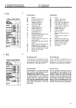
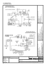
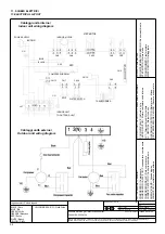
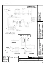
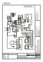
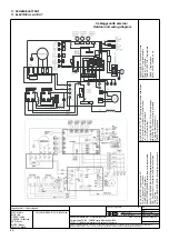
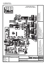
11. SCHEMI ELETTRICI
11. ELECTRICAL LAYOUT
Schema elettrico per /
Electrical layout for:
OGGETTO /
OBJECT
5300 410A
MATERIALI /
MATERIALS
:
DIS:
REV:
SCALA /
SCALE
:
DATA /
DATE
: 17.02.2005
DISEGNO \
DRAWING
:
INDICE /
INDEX
:
Disegno proprietà della ditta - a termine di legge è fatto vietato riprodurlo o di renderlo comunque noto a terzi senza autorizzazione
Drawing property of the company - you may not copy, reproduce or transfer it to third parties without authorization
Codice /
Code
:
N° Pezzi / N.
Pieces
:
Legenda colori - Colours legend
BLACK / Nero
YELLOW/GREEN (Y/G) / Giallo-Verde
BLUE / Blu
GREEN / Verde
ORANGE / Arancione
RED / Rosso
WHITE / Bianco
YELLOW / Giallo
Cablaggi unità interna /
Indoor unit wiring diagram
Cablaggi unità esterna /
Outdoor unit wiring diagram
ANION
GENERA
T
OR
/ Generatore ioni negativi
CN
-
Connectors
/ Connettori
COMPRESSOR
/ Compressore
COMPRESSOR CAP
ACIT
OR
/ Condensatore compressore
COMPRESSOR RELA
Y
/ Relé compressore
CURRENT DETECT
/ Controllo assorbimento
DISPLA
Y BOARD
/ Scheda display
F
A
N
MOT
OR
/ V
entilatore unità esterna
F
AN CAP
ACIT
OR
/ Condensatore ventilatore
FOUR-W
A
Y
V
A
L
V
E
/ V
alvola a 4 vie
INDOOR
MOT
OR
/ Motore ventilatore unità interna
JX1
-
T
erminal block
/ Morsettiera
MICROSWITCH
/ Micro-interruttore
N - NEUTRAL
/ Morsetto neutro
OVERLOAD RELA
Y
/ Relé termico - klixon
OXYGEN
ENRICHMENT
/ Arricchitore ossigeno
PLASMA / Sistema plasma
PIPE
TEMPERA
TURE
SENSOR
/ Sensore evaporatore
POWER SUPPL
Y
/ Aliment
azione
ROOM TEMPERA
TURE
SENSOR
/ Sensore ambiente
STEP MOT
OR
/ Motore alette
TRANSFORMER
/ T
rasformatore
4-W
A
Y
/ V
alvola a 4 vie


