background image


49 

     
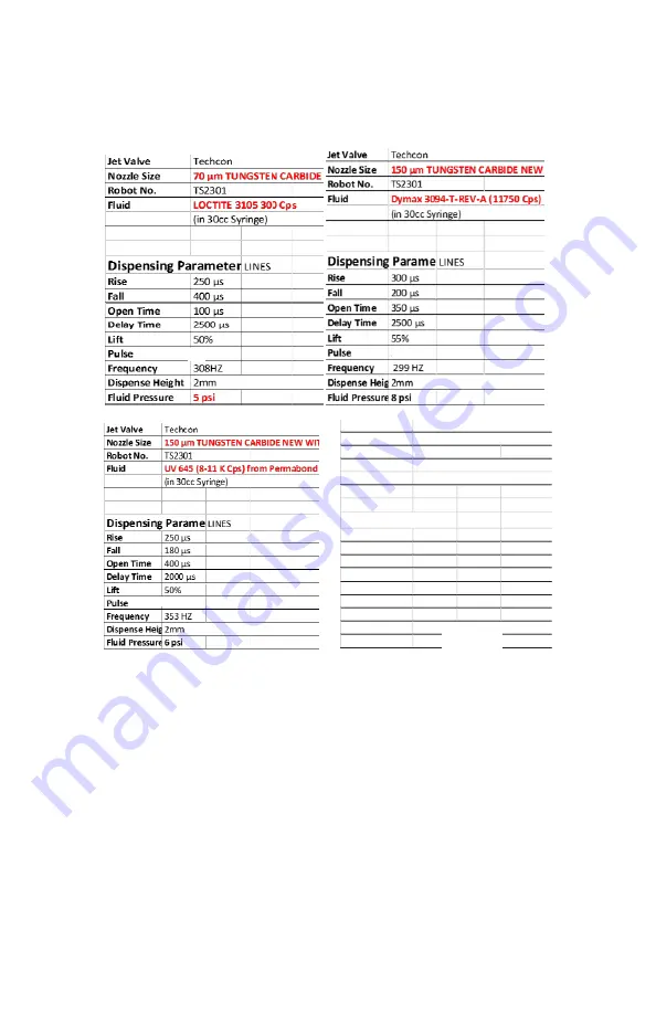
11.3   Sample parameters 


Note: 

parameters shown are for references only


Controller
Jet Valve
Nozzle Size
Robot No.
Fluid

Dispensing Parameters:

LINES

Rise

500 µs

Fall

180 µs

Open Time

800 µs

Delay Time

2200 µs

Lift

60%

Pulse

2

Frequency

272 HZ

Dispense Height
Fluid Pressure

60

(in 30cc Syringe)

2mm

Techcon

150 µm ceramic

TS2301

RHEOTEMP 768G (200-300K Cps)

PV UNIT FROM CHINA

Equipment:

75 Psi 

Summary of Contents for TS9800 Series

Page 1: ...Techcon Systems TS9800 Series Jet Valve User Guide...

Page 2: ...fety Instructions 6 3 Function 6 4 Mounting Connection 6 5 Setup 7 VALVE SETUP AND CLEANING 7 1 Valve Removal 7 2 Installation of new nozzle insert 2 7 3 Cleaning 8 TS9800 JET VALVE 8 1 Valve Modules...

Page 3: ...ode 9 5 9 Service Mode 9 5 10 Wi Fi Not available 9 5 11 IOT Remote Communication 9 5 12 Software Update 10 SPARE PARTS AND SCHEMATICS 10 1 Tappets Nozzle Inserts 10 2 Tools 10 3 Jet Valve s parts lis...

Page 4: ...cies up to 1500 Hz average frequency should not exceed 800 Hz and parameter settings must be followed The usage of media which affects the functioning of the TS9800 System must be avoided 1 4 Technica...

Page 5: ...ng the valve on any hard surface For cleaning the valve use a damp isopropanol cloth and make sure that no fluid leaks into the valve e g via connectors Never connect the TS9800 Jet Valve to a control...

Page 6: ...2 Jet Valve Controller TS980 3 Nozzle Insert order separately 4 Actuator Cable 3 to 2 pin connectors 5 Sensor Cable 6 to 5 pin connectors 6 Heater Cable 4 pin connectors This cable is available only i...

Page 7: ...and manufactured to the strictest degree of precision insuring world class accuracy and repeatability in drop to drop dispensing volume Jet Valve s compact size and modular design aids integration int...

Page 8: ...ecting the plug must be locked in place by turning the locking nut on the cable s mating connector a quarter of a turn in clockwise direction The 3 pin cable supplies the power for the piezo stack fro...

Page 9: ...ion to the warning and caution notices Step 1 Using the provided nozzle adjustment tool 1 to remove the nozzle adjustment nut bushing assembly 2 and protective nylon washer 3 Step 2 Use the provided n...

Page 10: ...the vertical position to prevent the nozzle insert from dropping out Step 4 Slowly screw the nozzle adjustment nut into the bushing nozzle insert assembly Caution Continue to hold the assembly in the...

Page 11: ...o 2 pins to the ACTUATOR port 12 Caution After connecting tighten the locking sleeve to secure the connection Connect the power cord to the DC IN port 13 Wi Fi antenna Not available Step 9 Connect the...

Page 12: ...ch the Login icon to enter the login screen Step 2 Enter the default password 0000 in the password window Then touch Accept icon to save and exit Attention For changing the password refer to section 9...

Page 13: ...bration icon Step 4 Use the nozzle adjustment tool to slowly and gently screw clockwise the nozzle unit onto the fluid manifold until it stops against the tappet Then touch the Start icon Step 3 The s...

Page 14: ...low the green zone does not make a significant difference for the precision of the dispense process if the yellow circle is inside the green zone Step 5 If the nozzle unit is un screwed too far out th...

Page 15: ...arks You can leave the calibration procedure by touching the Accept icon The calibration can only be confirmed by touch the Accept icon when the yellow circle is inside the green zone If you shut down...

Page 16: ...start signal for both or dot mode When in line mode start can only be activate or trigger by an external devised Attention To de air removal of air in the system after going through a calibration proc...

Page 17: ...Time This is the time between two dispense pulses It is adjustable in 1 s Percentage Lift Lift of Tappet This value corresponds to the stroke of the tappet It is entered in percent of the maximum stro...

Page 18: ...e starting to dispense aggressive fluid Be cautious that the media you want to dispense is applicable for use with a heating system Warning When using the Jet Valve with heater please consult with the...

Page 19: ...module Step 2 Use the 4mm hex wrench to install the provided M6 screw from the bottom to secure the heat guard in place Caution Do not over tighten the screw since it can damage the heat guard Step 3...

Page 20: ...in the password window Then touch Accept icon to save and exit Attention For changing the password refer to section 9 5 1 Step 3 Touch the Temperature icon to turn the heater ON and the icon will tur...

Page 21: ...s temperature reading at the bottom of the screen Once this temperature reaches the correct temperature setting then start the dispensing Warning Do not touch nozzle or fluid manifold with your finger...

Page 22: ...ection 7 3 for cleaning instructions 6 After replacing the new valve or new control unit repeat section 4 2 for setup and section 4 3 for nozzle calibration 7 2 Installation of new nozzle insert 1 Tur...

Page 23: ...ge cycles to remove air bubble from the nozzle replacement Wipe and Clean the nozzle tip and the system is now ready for dispensing Attention Inspect the nozzle s cleanliness under microscope if avail...

Page 24: ...th an appropriate cleaning solution to the valve then connect the syringe to the supply pressure Touch and hold the Purge icon on the controller to purge the system Run the purge until the system is c...

Page 25: ...ed for whatever reasons on a regular basis the tappet seal should also be replaced on a regular basis 6 Remove the tappet seal 3 from the fluid manifold 4 by inserting the provided tappet seal tool fr...

Page 26: ...e fluid manifold until the seal is fully engaged with a click noise 7 Using the Phillips screwdriver to remove the plug screw 9 with O ring 10 items 9 10 come as one piece 8 Remove the inlet Luer lock...

Page 27: ...bath for about 15 30 minutes Caution The nozzle insert can be cleaned and pierced through with special nozzle insert wire using the Pin Vice Pay attention to the nozzle insert diameter and choose the...

Page 28: ...nt PTFE Ethanol non resistant resistant resistant Heptane resistant non resistant resistant Hexane resistant non resistant resistant Isopropanol resistant resistant partially resistant Methylene chlor...

Page 29: ...ET VALVE 8 1 Valve Modules The TS9800 Series consists of three basic modules Actuator System module 1 Fluid Manifold module 2 Nozzle Unit module 3 Figure 5 TS9800 Jet Valve Figure 6 Jet Valve s intern...

Page 30: ...g the fluid leakage With the high viscosity fluid the valve will leak very slowly or not at all In order to eliminate the fluid leakage the supply pressure to the material syringe must be disconnected...

Page 31: ...grated into your existing setup 8 4 Materials applied Only high quality materials are used to manufacture the TS9800 Jet Valve System All fluid contacting parts consist of high alloyed rust proof and...

Page 32: ...rage spaces 50 49 STD program a P prog Colour of display Yes White backlighting Maximum heating temperature 90 C Heating circuits 1 Circuit I fluidic module heating Interfaces 11 DC power plug 24 VDC...

Page 33: ...33 9 3 Features Figure 8 Rear face of the Jet Valve Controller Figure 7 Front Face of the Jet Valve Controller Wi Fi Antenna Not Available...

Page 34: ...d Service Mode Wi Fi Setting Not Available Remote Server USB Application Update Dot Mode Line Mode Continuous Cycle Repeat Mode Rise Time Fall Time Open Time Delay Time Percentage Lift Pulse Valve Ope...

Page 35: ...the password touch the Change Password icon 5 Enter the old password then enter the new password 6 Touch Accept icon to save and exit 9 5 2 Disable Password protection keep controller in Unlock Mode...

Page 36: ...touch the unlock icon The unlock icon will switch to an lock icon indicating that the login icon will lockup with every login and logout 3 Touch Accept icon to save and exit 9 5 4 Reseting Master pas...

Page 37: ...parameters can be accessed from the home screen 1 Touch Rise Time icon to enter the setup screen 2 Touch the up and down arrows to set the desired rise time in s Caution The minimum rise time is 80 s...

Page 38: ...s and the maximum fall time is 1999 s 9 Touch the Accept icon to exit 10 Touch the Delay Time icon to enter the setup screen 11 Touch the up and down arrows to set the desired delay time in s 12 Touch...

Page 39: ...uency based on the entered dispensing parameters 9 5 6 Calling up Dispensing Parameters The controller has 50 memory cells store all dispensing parameters 1 Touch the forward or backward arrow to sele...

Page 40: ...ggle between the line or dot icons to switch mode Note switching from Line to Dot mode may required a re entry of a specific number of pulses desired to run the parameter or setup 1 2 Touch Run icon t...

Page 41: ...t will toggle to a valve Close icon close position is a normal operation mode Caution The valve does not jet the material in this mode the material flows under regulated pressure only 9 5 10 Connect t...

Page 42: ...m Number 6 Use any TCP IP tool setup as a server to remotely update Program Number Profile Data Profile Data example 1 cycleCount 6012 delay 1000 dutyCycle 7 dwell 300 fallTime 300 mode 0 nozTemp 25 n...

Page 43: ...py it to a blank USB thumb drive Caution The software file must be placed in the root directory 2 Insert the USB drive into the USB port located in the back of the unit 3 Touch the Settings icon to en...

Page 44: ...LE INSERT TUNGSTEN CARBIDE 0 30MM DIA 7511 0140 40 NOZZLE INSERT TUNGSTEN CARBIDE 0 40MM DIA 7511 0150 05 NOZZLE INSERT ZIRCONIA CERAMIC 0 05MM DIA 7511 0150 07 NOZZLE INSERT ZIRCONIA CERAMIC 0 07MM D...

Page 45: ...30 FLUID MANIFOLD W O HEATER SS 1 5 2800 0981 MOUNTING SCREW FLUID MANIFOLD 2 6 7511 9170 ASSEMBLY NOZZLE BUSHING SS 1 6A 7511 0480 NOZZLE BUSHING SS 1 6B 3300 0662 O RING NOZZLE BUSHING 2 7 7511 0140...

Page 46: ...n 0 5C 7 REMOTE TEMP_IN I AN Remotely set temperature on the nozzle heater when heater has been switched ON control signal on PIN 12 0 90C Range 200mV 10C 8 24V 200mV 10C 9 NC 10 NC 11 NC 12 HEATER CO...

Page 47: ...no for evaluation Check connection of actuator cable Manual dispensing must be in Dot Mode Line Mode required external trigger check external triggering device Nozzle maybe clogged Syringe pressure mu...

Page 48: ...e The longer the delay the further the dots as it try to connect the dots to form a line it may not form solid line Higher lift for stronger punch jet The vale is more stable with lift higher than 40...

Page 49: ...e Nozzle Size Robot No Fluid Dispensing Parameters LINES Rise 500 s Fall 180 s Open Time 800 s Delay Time 2200 s Lift 60 Pulse 2 Frequency 272 HZ Dispense Height Fluid Pressure 60 in 30cc Syringe 2mm...

Page 50: ...manufacturer arising from this warranty exceed the purchase price of the equipment This warranty is only valid if the defective product is returned as a complete assembly without physical damage The m...

Page 51: ...eturned un clean it will be sent back to the customer In any case the customer is liable for defects caused by insufficient decontamination This includes explicitly damage to persons and property Each...

Page 52: ...90630 USA Tel 1 714 799 9910 Fax 1 714 230 2303 E mail oemorders okinternational com Techcon Systems European Corporate Office Eagle Close Chandler s Ford Industrial Estate Eastleigh Hampshire SO53 4...

Reviews: