background image

10 

TASCAM DR-701D

2 – Names and functions of parts

NOTE

Sometimes a 

Battery Low

 warning appears when 

recording or conducting other demanding operations even 

when battery power remains.

5

  HDMI connection status

This shows the HDMI connection status.
No indicator: ; HDMI not connected

: HDMI connected
: HDMI connected (clock sync)

6

  Recording setting status

These show whether or not recording is enabled. (see 

“Setting channels to record” on page 25)

      : recording not enabled
      : recording enabled

7

  Phantom power status

These show whether phantom power is on or off.(see 

“Setting phantom power” on page 22)
No icon: Phantom power off

: Phantom power on

8

  MIX recording setting status

: MIX recording off

: MIX recording on

9

  Level meters

These show the levels of the input and playback signals.
The dotted lines at the −20dB (

b

 mark) and −12dB 

positions are guides for input level adjustment.

0

  Remaining time 

When playing back, this shows the remaining time (hours: 

minutes) of the current file.
When recording, this shows the remaining time (hours: 

minutes) of the SD card.

q

  Peak values in decibels (dB)

During playback, the maximum level that occurs in a fixed 

period of time is shown in decibels for each channel.
During recording, the peak input level values are shown in 

decibels.

w

  Project name

This shows the name of the project being recorded or 

playing back.
A project is a group of files used for recording/playback.

e

  Trim values

These show the settings of the 1/2/3/4 knobs.

r

  GANG status

These show the GANG operation status of the 1/2/3/4 

knobs.(see “Setting the GANG operation mode” on page 

34)

: Set to GANG group 1
: Set to GANG group 2

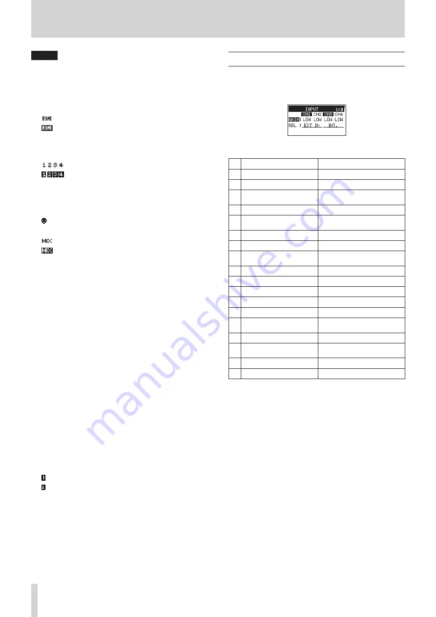
Menu structure

The first time, press the MENU button to open the 

INPUT

 page 

of the menu. In the future, press this button to reopen the menu 

page that was last open.

The Menu Screen has 18 pages organized by types of menu 

items.

Page name

Meaning

1

INPUT

Make input settings.

2

MIXER

Make built-in mixer settings.

3

PHASE/DELAY

Make input phase settings and 

compensate for mic distances.

4

LEVEL CONTROL

Make input level settings.

5

TRIM GANG

Make GANG operation 

settings.

6

OUTPUT LEVEL

Make output level settings.

7

MIC POWER

Make mic power settings.

8

RECORD

Make recording channel 

settings.

9

REC SETTING

Make recording settings.

10

FILE

Make file settings.

11

MEDIA

Make media settings.

12

TIME CODE

Make time code settings.

13

SLATE TONE

Make slate tone settings.

14

HDMI AUDIO 
ASSIGN

Set HDMI output audio assign-

ments.

15

METER/TRIM

Make meter and trim settings.

16

POWER MANAGEMENT

Make power management 

settings.

17

REMOTE

Make remote control settings.

18

SYSTEM

Make system settings.

Summary of Contents for DR-701D

Page 1: ...D01276520B DR 701D Linear PCM Recorder for DSLR REFERENCE MANUAL...

Page 2: ...reversal for individual channels 21 Set the power sources used by mics 22 Setting phantom power 22 Setting the phantom power voltage 22 Setting plug in power 23 Using the limiter 23 Setting automatic...

Page 3: ...and Information 36 Setting the file name format 36 Setting the WORD item 36 Resetting the count 36 Format an SD card 36 Adjusting the display contrast 37 Setting the peak hold time 37 Setting trim ope...

Page 4: ...control can be used to control recording levels in response to input signal volumes Multiband limiter can automatically reduce just parts with input levels that are too high to suitable levels Low cut...

Page 5: ...use of this product Properties copyrighted by third parties cannot be used for any purpose other than personal enjoyment and the like without the permission of the right holders recognized by copyrig...

Page 6: ...election menu 0 2 7 button When the Home Screen is open and the unit is stopped press this button to start playback When a file or folder is selected on the Browse Screen press this button to return t...

Page 7: ...S jack CAUTION Before connecting headphones lower the PHONES volume to the minimum level Failure to do so could result in a sudden loud noise that could harm hearing for example d PHONES jack 3 5mm st...

Page 8: ...on the camera see Camera connections on page 16 v OUT jack 3 5mm stereo mini jack Use a stereo mini jack cable to connect this with the camera external input jack Use the OUTPUT LEVEL page CAMERA ite...

Page 9: ...ode 1 Time code reception status This shows the time code reception status see Inputting time code and adding recording start times to files on page 28 No indicator time code not being received time c...

Page 10: ...g the peak input level values are shown in decibels w Project name This shows the name of the project being recorded or playing back A project is a group of files used for recording playback e Trim va...

Page 11: ...LE page NAME TYPE Set the file name format page 36 WORD Set the file name text COUNT INIT Reset the file number MEDIA page BROWSE Work with files and folders on the SD card page 31 page 32 NEW FOLDER...

Page 12: ...E For a setting item that shows CH1 CH2 CH3 CH4 press the DATA dial to move the cursor to the setting value of the next channel in order In addition pressing a number button will also move the cursor...

Page 13: ...TASCAM BP 6AA external battery box both sold separately to power the unit Using an AC adapter sold separately Use the included USB cable to connect the TASCAM PS P515U AC adapter to the unit s USB por...

Page 14: ...it before turning the unit on off standby Do not use headphones when turning the unit on off standby Loud noises could damage the speakers or harm your hearing Turning the unit on To start the unit wh...

Page 15: ...t cover 2 Insert an SD Card into the slot as shown in the illustration until it clicks into place Removing the card 1 Open the front cover 2 Press the SD card in gently and then release it to allow it...

Page 16: ...cord audio from this unit with a camera Use a commercially available 3 5mm stereo mini plug cable to connect the OUT jack on the right side of this unit with the external mic input on the camera 8 8 T...

Page 17: ...Recording an external device LINE IN Use stereo plug cables to connect to the output of an external audio device Audio devices CAUTION Reduce the output level of the external audio device if the inpu...

Page 18: ...ult 0dB 3 When finished press the MENU button to return to the Home Screen CAUTION Hardware gain switching occurs at 3 points between 0 dB and 1 dB between 12 dB and 13 dB and between 30 dB and 31 dB...

Page 19: ...HDMI 2 input sound HDMI3 Monitor the HDMI 3 input sound HDMI4 Monitor the HDMI 4 input sound HDMI5 Monitor the HDMI 5 input sound HDMI6 Monitor the HDMI 6 input sound HDMI7 Monitor the HDMI 7 input so...

Page 20: ...ecorded sounds or signals from being distorted due to excessive input levels and to prevent them from being so low that they are below the noise floor In addition to manual adjustment the unit has lim...

Page 21: ...hile adjusting the input levels or recording connect headphones to the PHONES jack Use the PHONES jack volume control to adjust the monitoring level Compensating for mic distances Use this function to...

Page 22: ...ndenser microphone before connecting to or disconnecting from an IN 1 IN 2 IN 3 or IN 4 connector confirm that the phantom power for that jack is OFF If you connect or disconnect a mic while phantom p...

Page 23: ...to the input level to set the recording level so that distortion does not occur even when loud sounds are input 1 Select the LIM item on the LEVEL CONTROL page see Menu operation procedures on page 12...

Page 24: ...U button to return to the Home Screen Setting the recording file type file format and sampling frequency Use the items on the REC SETTING page to set the recorded audio file format before you start re...

Page 25: ...ny channel 1 2 3 or 4 that also has its recording setting OFF Recording MONO STEREO POLY 6ch Starting recording 1 Press the record 0 button This starts ordinary recording When recording starts the REC...

Page 26: ...wer input level for safety Two recorded files one with higher input level and one with lower input level are saved individually NOTE Make the input level setting for the ordinary recording in the usua...

Page 27: ...both units can record the same tone signals to their files These tones can be used as guides to synchronize the files in video editing software For details about how to connect the unit with a DSLR ca...

Page 28: ...his sets the source of input time code 1 On the TIME CODE page select the SELECT item see Menu operation procedures on page 12 2 Set the time code input source Option Meaning LTC default Time code is...

Page 29: ...12 00 00 00 15 00 16 00 11 00 12 00 00 00 15 00 16 00 ON POWER ON POWER ON 11 00 12 00 15 00 16 00 14 00 13 00 CAPTURE CAPTURE POWER OFF T C GEN MODE POWER OFF GEN Time Master Timecode 10 00 11 00 12...

Page 30: ...53 11 34 46 18 WAV BWF 24 bit 2 channel 44 1 kHz 8 23 33 35 134 24 48 kHz 7 42 30 51 123 28 96 kHz 3 51 15 25 61 44 192 kHz 1 55 7 42 30 52 The recording times shown above are estimates They might dif...

Page 31: ...that file The folder that contains this file becomes the current folder and new recorded files will be saved in this folder This folder also becomes the playback area When a folder is selected press t...

Page 32: ...L This cancels the operation for the selected highlighted folder and closes the pop up menu Creating a new folder Using the MEDIA menu page to create a folder 1 On the MEDIA page select the NEW FOLDER...

Page 33: ...ack positions When the Home Screen is open use the 4 and 3 buttons to jump to the nearest mark in that direction Press the 4 button when the current playback position is before the first mark to jump...

Page 34: ...ding with a mid side mic Use this also when playing back mid side files that were recorded without decoding 4 When finished press the MENU button to return to the Home Screen 5 When recording a decode...

Page 35: ...dial to connect the unit with the computer The USB connected message appears on the display Make sure that the SD card is inserted in the unit properly NOTE Power is supplied from the USB port if the...

Page 36: ...the DATA dial to reset the count The numbers added to file names characters set by WORD or the date created after this will restart from 0001 Format an SD card Follow this procedure to format an SD c...

Page 37: ...power management settings on the POWER MANAGEMENT page see Menu operation proce dures on page 12 Setting the type of batteries Use the BATTERY TYPE item to set the type of batteries used This setting...

Page 38: ...This shows the audio file type Bit length stereo mono and sampling frequency Hz also appear 8 8 TITLE This shows the project name 8 8 DATE Date of file creation 8 8 SIZE This shows the file size Card...

Page 39: ...n function REC 2 STOP REC SLATE 4 When finished press the MENU button to return to the Home Screen Using the footswitch Press the pedals of the footswitch to use the operations assigned to them on the...

Page 40: ...folder MBR Error Init CARD The SD card is not formatted properly or the card is broken Change the card or press the DATA dial while this message is being shown to format the card Formatting will eras...

Page 41: ...und is output Is the monitoring system connected properly Is the volume of the monitoring system minimized Is the output level setting of the unit minimized 8 8 Recording is not possible Check connect...

Page 42: ...ut impedance 10 k Maximum input level 10 dBV Minimum input level 50 dBV Mic input gain when trim at max LOW 3 dB MID 11 dB HI 26 dB HI 38 dB 8 8 IN connector Connector 3 5mm 1 8 stereo mini jack Input...

Page 43: ...s Channels 1 2 unused built in mic used for channels 3 4 Phantom power unused HDMI not connected Recording 2ch 48kHz 16 bit WAV files About 4 00 Channels 1 2 used channels 3 4 unused 3mA phantom power...

Page 44: ...in mic used for channels 3 4 Phantom power unused HDMI not connected Recording 2ch 48kHz 16 bit WAV files About 12 30 Channels 1 2 used channels 3 4 unused 3mA phantom power used for 2 channels HDMI n...

Page 45: ...TASCAM DR 701D 45...

Page 46: ...o Churubusco 364 Colonia Del Carmen Delegaci n Coyoac n CP 04100 M xico DF M xico TEAC UK Ltd http tascam eu Phone 44 8451 302511 2 Huxley Road Surrey Research Park Guildford GU2 7RE United Kingdom T...

Reviews: