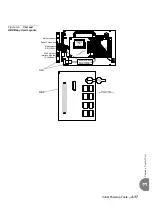
Initial Powerup Tests
3-23
Sha
re
d
Service and
Peri
pheral
Car
d
T
est
3
0
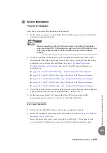
Preparing for Initialization
After the software has been installed and initialized:
1.
In the expansion cages, verify that the PS19 or PS500 power switch is in the OFF
position (turned downwards).
Before proceeding, verify that all power supply units within the expansion
cages are turned OFF. If the expansion cages are turned ON before the main
cage, the peripheral cards within the expansion cages will not initialize
properly.
2.
Check the position of shared service and peripheral interface cards that will be
inserted into the system card cage. Observe any order previously directed or any
established convention of the distributor. See
Peripheral Interface Card Installation
and
use the Card Placement Diagram, as
described on:
page 2-42, Coral IPx 800M Main Cage - Peripheral Card Placement Diagram
page 2-43, Coral IPx 800X 1st Exp. Cage - Peripheral Card Placement Diagram
page 2-44, Coral IPx 800X 2nd Exp. Cage - Peripheral Card Placement Diagram
page 2-45, Coral IPx 500X 1st Exp. Cage - Peripheral Card Placement Diagram
page 2-46, Coral IPx 500X 2nd Exp. Cage - Peripheral Card Placement Diagram
3.
Verify that all shared service and peripheral cards in the main cage and expansion
cages protrude from the cage by approximately 1 inch (2.5 cm).
4.
In the main cage, attach the Program Interface (PI) device cable to KB0
programming port connector on the front side of the MEX-IP2.
Main Cage Initialization
1.
Verify that the MEX-IP2 control card has been initialized properly.
2.
Insert the peripheral cards completely into their card slots. See
Inserting a Coral Circuit Card
Insert the cards fully, one by one, from right to left (slot# 1-9) in adjacent card
slots, so that the installation corresponds with the uniform numbering plan.
2
System Initialization
Summary of Contents for Coral IPx 800 Series
Page 2: ......
Page 4: ......
Page 10: ...vi...
Page 16: ......
Page 22: ......
Page 28: ......
Page 32: ...1 4 Coral IPx 800 Installation Manual Document Description 1 NOTES...
Page 34: ...1 6 Coral IPx 800 Installation Manual Special Symbols Used in this Document 1 NOTES...
Page 40: ......
Page 48: ...2 8 Coral IPx 800 Installation Manual Site Inspection 2 NOTES...
Page 90: ......
Page 116: ...3 26 Coral IPx 800 Installation Manual Shared Service and Peripheral Card Test 3 NOTES...
Page 118: ...3 28 Coral IPx 800 Installation Manual Installation Wrap up 3 NOTES...
Page 120: ......
Page 126: ......
Page 142: ...5 16 Coral IPx 800 Installation Manual Protection Devices 5 NOTES...
Page 150: ...5 24 Coral IPx 800 Installation Manual Terminal Data Communication Ports RS 232E 5 NOTES...
Page 242: ......
Page 278: ...6 38 Coral IPx 800 Installation Manual Cage Description and Installation 6 NOTES...
Page 292: ...6 52 Coral IPx 800 Installation Manual Coral IPx 800X Expansion Cage Description 6 NOTES...
Page 312: ...6 72 Coral IPx 800 Installation Manual System Configuration Options Coral IPx 800 6 NOTES...
Page 314: ......
Page 352: ...7 38 Coral IPx 800 Installation Manual PS19 DC D Power Supply Unit with Duplication 7 NOTES...
Page 368: ......
Page 372: ...8 4 Coral IPx 800 Installation Manual Common Control Cards 8 NOTES...
Page 382: ...8 14 Coral IPx 800 Installation Manual Software Authorization Unit SAU 8 NOTES...
Page 384: ...8 16 Coral IPx 800 Installation Manual MAP 8 NOTES...
Page 386: ...8 18 Coral IPx 800 Installation Manual LIU 8 NOTES...
Page 392: ......
Page 396: ...8 26 Coral IPx 800 Installation Manual HDC Card High Density Control 8 NOTES...
Page 399: ......

